


April 27, 2020
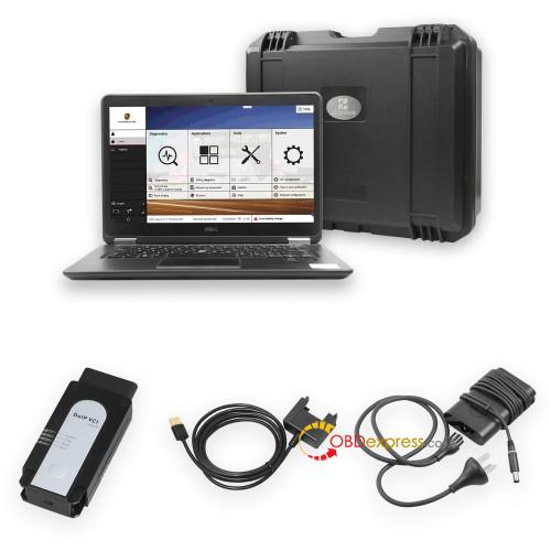
This is a way to setup the Porsche PIWIS 2 software as a virtual machine (VM) inside Oracle’s VirtualBox, which is free VM software.
This is just the software. You clearly need to purchase the Piwis2 Tester hardware (cable) to connect to the car. You can just setup the VM and use the simulation mode in PIWIS to have a play prior to purchasing the hardware if you like.
To the people who made this available, I take my hat off to you. There was clearly a lot of effort from some very smart people that allowed someone like me to get access to the software.
Background info:
PIWIS
2 runs natively in Windows XP. XP is no longer supported, and it is
difficult to acquire an old computer that runs XP and keep it running.
Using the software in a VM, whilst slower, will ensure you are able to
keep the software forever regardless of the computer you use. I use a
laptop that was pretty slick back in 2014, but is pretty slow by today’s
standards. It takes a few minutes to get the VM loaded, but after that
it’s as fast as any diagnostic software I’ve used in the past on other
car types.
A while ago I was fortunate enough to stumble on a link to PIWIS 2 as a bunch of files that, through a specified process got software loaded and licensed on either an XP computer or a VM. Not having an XP computer, I went down the road of creating a VM.
Once the VM was created and the software licensed, it was a simple process of making a backup of the VM. This backup can then be imported to VirtualBox on any computer as an XP image with the PIWIS software is installed. There are only a few things that need to be done once the VM is created so that it’s good to go. It’s a surprisingly simple process.
Requirements:
A reasonably fast computer. Most modern laptops will easily do the job.
A
minimum of 1.5GB of excess RAM (this is what is going to be allocated
to the VM). Use Task Manager to see what is normally used. 8GB of RAM on
a standard Windows 10 install should easily have enough to spare. 4GB
probably won’t.
A minimum of 20 GB of spare hard drive capacity. This is what VirtualBox and the VM will take once installed.
For those who don’t know what a VM is, Google it and do some reading. Very simply you are creating a separate computer (guest) within your computer (host). You allocate resources from your host (RAM, etc) and run the guest within a window on your normal desktop.
Here’s how to set it up.
1.
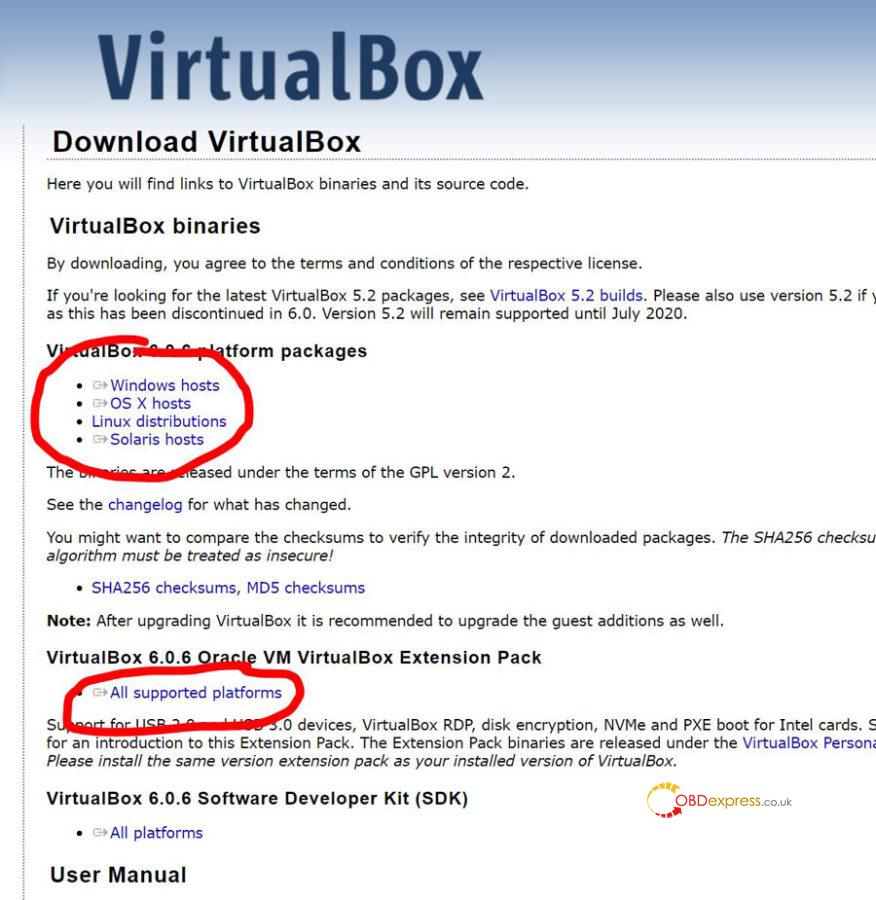
Google ‘VirtualBox downloads’. Go to the download page and download the
latest version of VirtualBox for the platform you use (PC, mac, etc).
On the same page, download the extension pack. This isn’t platform
specific and is the same file for all operating systems.
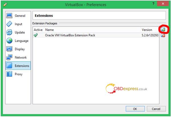
2. Log into your computer into the administrator account. Install VirtualBox. Once installed, open the program and then install the extension pack. You can’t install the extension pack unless you are logged in as an administrator. Installing the extension pack needs to be done from the preferences window of the VirtualBox program. If required, Google for how to do this. There are lots of videos how. Image below is what it should look like after the extension pack is installed. If not installed, it won’t be listed. Click the + button (red circle), find the extension pack file you downloaded and select it to be installed.
3. Once VirtualBox and the extension pack have been installed you can log out of the administrator account if you want and login where you normally work.
4. Download the .ova file from the following link. It’s about 12.3 GB. This is the backup file of the VM. Depending on the browser you use, it might sometimes give a network error, and you will have to start again. Try another browser if you are getting this error. Also, when you ask to download the file, google drive will give you a warning that the file size is too large to virus scan. The machine where I created the file uses up to date virus scanning software. I’m confident it’s clean, but only you can make the decision of whether to download. I’ve downloaded the file to other machines and created the VM with no problems.
https://drive.google.com/file/d/1ST3ZMgxvyufgvMNMlmany9Om4NpwDVny/view?usp=sharing
5. Open VirtualBox. Go to file, then import appliance. Go to the .ova file you just downloaded and select this. There are a few clicks of OK, and then allow the new VM to be created. It will take a few minutes.
6. If you have a cable, don’t connect it yet, we’ll do that later.
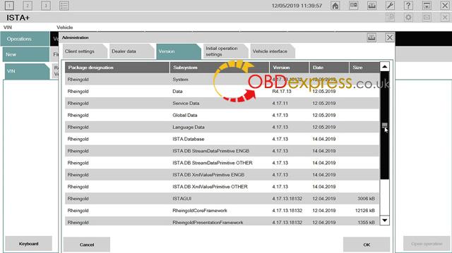
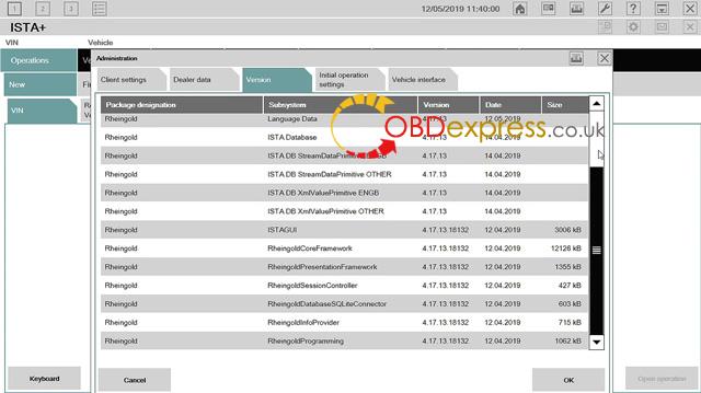
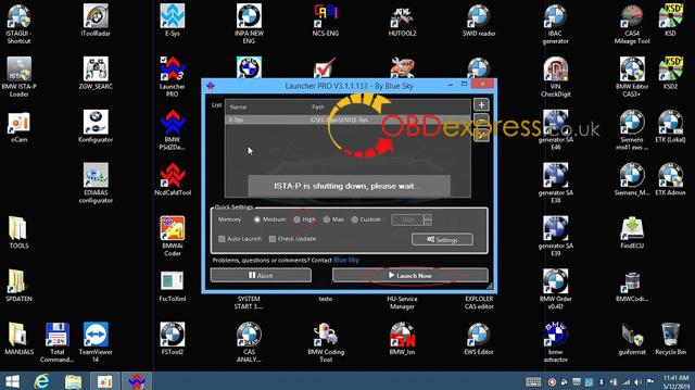
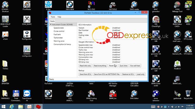
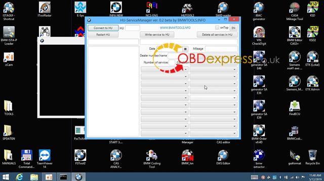
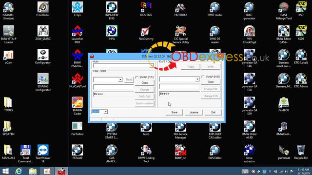
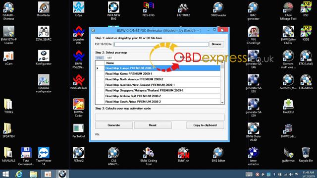
7. Click on the VM (should be called PIWIS) in the left pane and then click start. It will now start Windows XP. On the desktop, PIWIS is the car icon at the bottom.
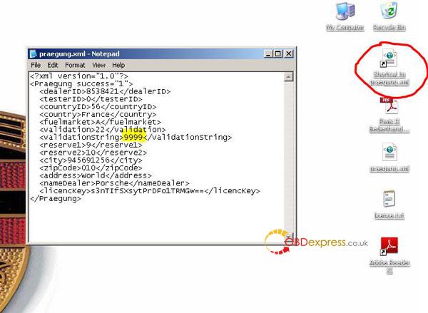
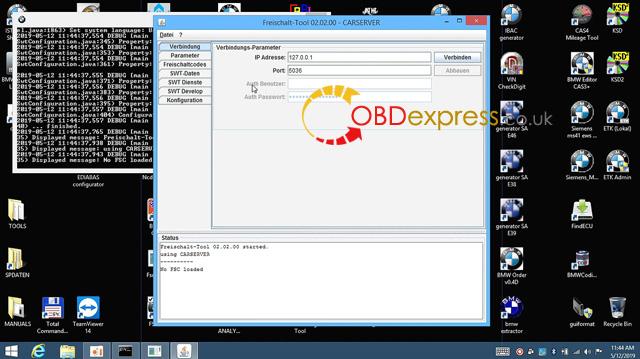
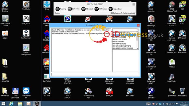
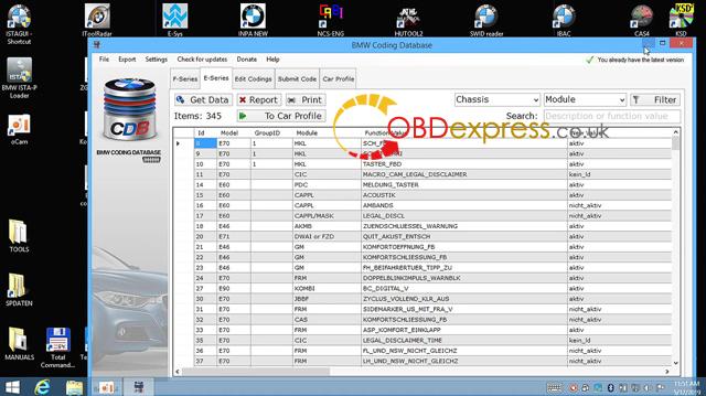
8. Right click on the ‘shortcut to praegeng.xml’ file and open in notepad. Go to the line that has ‘validationstring’ and change the ‘x’ to ‘9999’. This will now give the software a licence validation time of 9999 days. Save then close.
9. Click on the PIWIS shortcut. When PIWIS starts, select diagnosis and then select the car you have. If you don’t have a cable it will tell you this and give you the option of using simulation mode to continue.
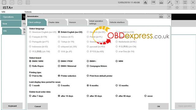
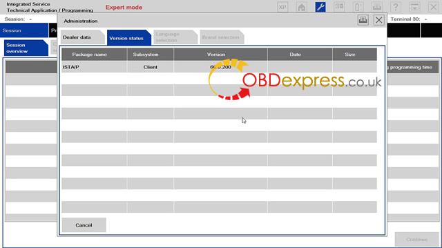
10. PIWIS is setup to operate in ‘V’ mode (after sales mode), which is what is used in the dealership. You can change to either of the other modes, E = developer, or P = production. When you initially open the program and you get the first page with the picture of the Cayman, click settings, then diagnostic configuration and then choose the model line. Click the mode tab at the top, and now you can go down to ‘operating mode’ and change the mode of the software. Save. Close. Now open the diagnostics for your car type and you should be in the new mode.
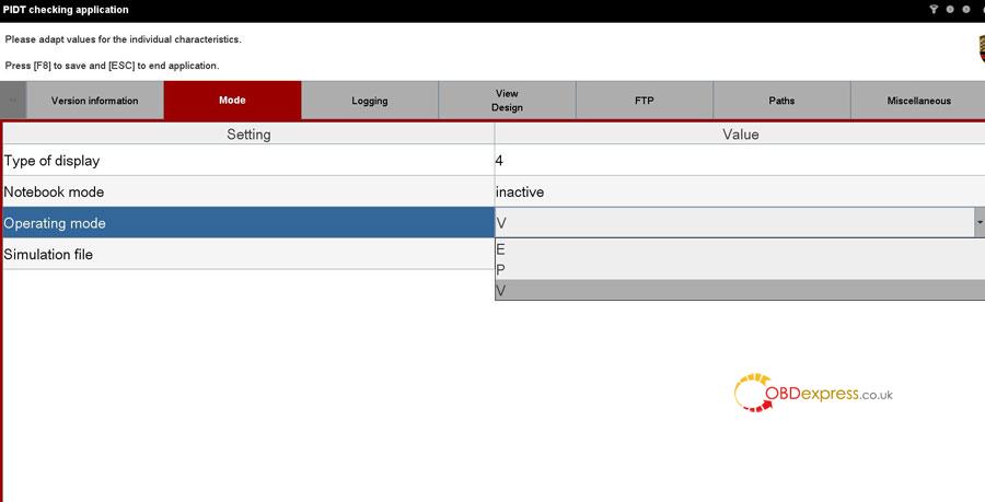
The vast majority of stuff you will want to change will be available in V (after sales) mode.
NOTE 1: The developer mode is in German only.
NOTE
2: Production mode doesn’t seem to work and locks you out of the
program. I would suggest not using this. If you accidentally do select
this, delete the VM (from the VirtualBox software window) and then
create a new VM from the ova file you downloaded.
Connecting the Piwis2 Tester cable.
There are a few things that need to be understood prior to trying to connect the cable.
– The cable will only be recognised by the computer when the plug is connected to the car and the ignition is turned on.
–
when you start the VM, the cable needs to be powered, and the VM needs
to be setup to immediately recognise the cable and mount it as the VM
starts. If it doesn’t do it when it starts, you won’t be able to connect
it afterwards once the VM is running.
To ensure this happens, do the following.
1. Open VirtualBox but don’t start the VM.
2. Turn ignition on (or start the car).
3. Have both cables connected to the interface, then plug into OBD port. Wait a few bananas.
4. Plug cable into computer.
5. Go to VirtualBox, Settings, USB. Click the small USB button on the right with the +, and then select the cable. Picture below shows what it should look like once done.
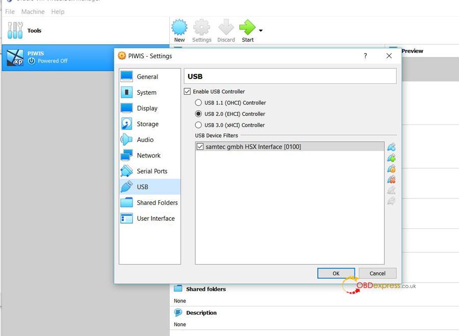
6. Now start VM. When the VM starts it should see the new hardware and try and automatically install the driver. Ask it to search for the driver when the wizard starts and then let it install.
7. Now start PIWIS. It should update the firmware on the cable hardware.
8. Now you should be able to open PIWIS and have all functionality.
9. Next time you use the software all the drivers will be loaded, but ensure you connect everything in the same order as described above (except the bits that are clearly for installing stuff).
NOTE: Every time I use PIWIS, prior to starting the VM, I conduct step 5 to check the cable has been recognised by VirtualBox. I simply click on the + and see what USB devices VirtualBox can see at that moment. The Samtec interface should be in the list that immediately appears. If you haven’t done everything in the correct order, you will see ‘unknown device’. If this is the case, start the process again. I find that if I do this, I don’t go through the whole process of starting the VM and then PIWIS to find out it hasn’t connected correctly.
Examples of hardware you will need. You don’t need a hard drive with the software loaded, which they will most likely try and sell you as well.
Piwis Tester II V18.1 Tester (hardware only)
http://www.obdexpress.co.uk/wholesale/porsche-piws2-tester-ii.html
Piwis Tester II V18.1 Tester + Panasonic CF30 Laptop + Software
http://www.obdexpress.co.uk/wholesale/piws2-tester-diagnostic-tool-for-porsche.html
Other details of the VM for those interested.
Guest additions doesn’t need to be installed as it is already in the ova file.
Two cores have been selected for processing. I initially used one and via Task Manager could see it was running at 100% for a lot of the time. Changing to two had it below 100% nearly all the time so I stuck with that. It was also noticeably faster when using two cores.
The most RAM I saw being used was about 950 MB. I’ve selected 1.5 GB to ensure it covers this easily. If you are short on RAM, you may want to tweak this.
Posted by: OBDexpress.co.uk at
06:17 AM
| No Comments
| Add Comment
Post contains 1652 words, total size 44 kb.
April 26, 2020
Free download Renault Can Clip V195 (03.2020) Torrent:
https://mega.nz/folder/4B4GXYRa#z19USPInTgniFvwe_EKSXw
No password! No risk!
Size: 4.29GB
Activation+ Patch2020:https://fex.net/ru/s/rokezfz
Size: 687KB
Region: All regions
Language: English,German, Danish, Spanish, Finnish, French, Italian, Norwegian, Dutch, Portuguese, Romania, Swedish.
Note:
You can choose the language you need when you install the software.
Once selected, the software language cannot be switched.
Version: v195
Developer: SPX
Platform: Windows7, WIN8, WIN10
Note: Starting with version CLIP 173, Windows XP is no longer compatible with CLIP.
Quantity of CD: 1 DVD DL
Year: 2020
Date of update: 03/2020
Tested 100% working CAN Clip V195:
http://www.obdexpress.co.uk/wholesale/can-clip-renault-diagnostic-tool-interface.html
Security: 100% tested, use with relief
Confirmed to work with Renault CAN CLIP interface such asSP19-A(best quality),SP19-C(good quality) andSP19-D(cheapest)
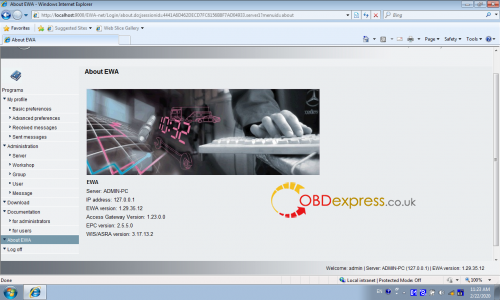
New features of Renault CAN CLIP V195:
-No new vehicle for this version.
-New Clip screen Capture button at the bottom of each screen (or taskbar)
-As
part of the migration from Windows 7 to Windows 10, the validity period
of the CLIP registration willgradually be decreased.
-Admission of the ACCEL portal: Bosch help function for the ADT probe (shortcut is available on the desktop)
-Documentation relating to the probe with these translations are available.
GENERAL INFORMATION:
1.In order for the return of the diagnostic files towards the central server to be more fluid, remember to connect Clip and close the session daily.
2.New ADT probe is available for sale.
3.Be careful to keep the old VI Alliance to make the legacy.
4.As part of the Windows 10, 64-bit migration project planned for 2020 for all clip entries, the period of validity of applications will gradually be reduced from one year to one month.
Warning:
1.Maintenance of the PANASONIC CF19 MK3 ceased in March 2018 and they can no longer be registered.
2.Maintenance of the Tecra A11 and CF19 MK2 ceased in January 2017 and they can no longer be registered.
V195 Can Clip for Renault Function:
1.See all the information relating to the vehicle
2.Computer test
3.Automatic test of all computers
4.Airbag test
5.Ccantool (OBD tests)
6.Base Doc (access to Technical Notes)
7.Physical measurements
8.Antipollution
9.Multimeter
Posted by: OBDexpress.co.uk at
07:15 AM
| No Comments
| Add Comment
Post contains 352 words, total size 31 kb.
April 22, 2020
Car model and year: Porsche 991
Purpose: to enable High Beam Assist
Which device:
Definitely,piwis tester iii for porsche
Question:
How does this work? I know what it’s suppose to do, but do I have to turn it on, or does it go into high beam assist automatically?
I can make it go into HBA and I can see the little dash icon illuminate ( the headlight with an "Aâ€). Is this the only way?
Advice:
Just making an assumption here, but if you leave the high-beam stalk in "low†position, the headlights will stay "dippedâ€; if you move it into "high†position, the auto function then takes over.
EDIT: Reading the manual it states "The function activates in darkness if the following conditions are present:
-Light switch positionAUTOis selected.
-Vehicle speed is more then approx 37 mph (60 km/h).
-High Beam Assistant is activated on the multi-function display in the instrument panel.
See the chapter "ACTIVATING AND DEACTIVATING HIGH BEAM ASSISTANT†on page 120.
-High Beam Assistant on is selected on the high beam stalk.
High beam assist is not available at speeds less then 20 mph (30km/h).â€
Pg 120:
Activating High Beam Assist:
1. Main menu: select "Vehicleâ€
>â€Settingsâ€
>â€Light & Visibilityâ€
>â€Exterior Lightsâ€
2. Select "Hi. beam assist.â€
3. Confirm your selection.
Activated/Deactivated
Apparently Activated or Deactivated remains selected when you turn off the car, i.e. you should not have to reset it each time you climb aboard..
once initiated, it remains functional to speeds as low as 30 km/h (18.7 mph).
I believe the factory thinking is you are supposed to be out of the city/town for it to work, so must exceed 60 km/h to initiate the functionality (the system assumes you are out of town if you are going 60 km/h=37 mph, as EU drivers "tend†to be kind of fastidious about speeds in town).
So you should be fine on your rural country road, as long as you don’t have to *****-foot around the bends!


Question:
Most people seem say the standard headlights are bixenon 25W. However with the "Bi-Xenon Headlights in Black incl. Porsche Dynamic Light System (PDLS)†($690) option they are 35W. Does anyone have any proof that the two are different?
Answer:
In Europe, any headlights putting out a certain number of lumens require both headlight levelling and a washing system. The standard (non-PDLS) lights lack the headlight washing nipples, so I suppose that’s evidence the light output is inferior.
the bulb for non-PDLS cars is 25W and the bulb for PDLS is 35W, and the above-mentioned reason is why PDLS includes headlamp washers. I can’t imagine why the GT4 would be any different from the other Porsche models in this case in bulb specs. Fwiw, the German GT4 catalog PDF specifically says that PDLS includes 35W bulbs on Page 23, although it doesn’t say that the standard is 25W.
Question:
It is stated in the catalogue that the regular system has 25W and the PDLS has 35W. What happens if you just upgrade the bulbs from 25W to 35W in the regular system?
I was wondering that myself, but I haven’t seen anybody talk about doing that. I suppose it’s possible the connector is a different size that physically prevents it, but even if it’s not, if the circuitry for the headlamp is also different when PDLS is optioned, then putting a higher-wattage bulb into a socket that isn’t designed to support it might shorten the life of the bulb and/or burn out the circuitry.
Answer:
That is true for 12V systems to an extent. Keep in mind that in Xenons you have a ballast that steps up the voltage tremendously. I’d be more worried about the supply lines, connections to or the ballast itself than the bulb. The other thing could be a sensor that can be controlled, adjusted viaPIWIS III, thereby throwing a code.
Posted by: OBDexpress.co.uk at
08:38 AM
| No Comments
| Add Comment
Post contains 662 words, total size 6 kb.
April 21, 2020
About some users requesting schematic of iprog. We have it here on obdexpress.co.uk.
EE_ADAPTER Ñхема Q1-Q8_BSS84

http://www.obdexpress.co.uk/upload/service/20042115874520647412.pdf
iprog_mainboard_sch:
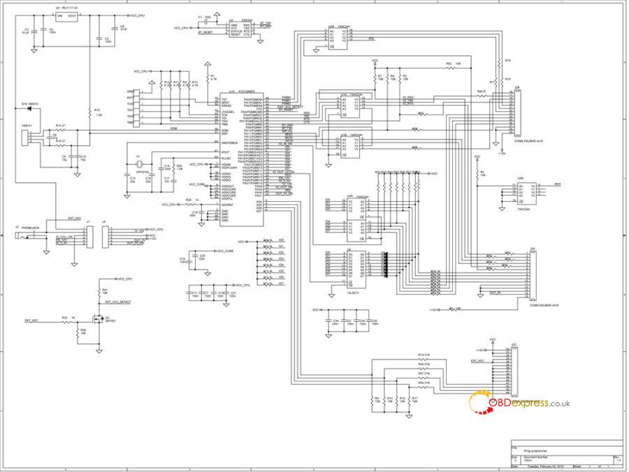
http://www.obdexpress.co.uk/upload/service/20042115874520675182.pdf
iprog_powerboard_sch
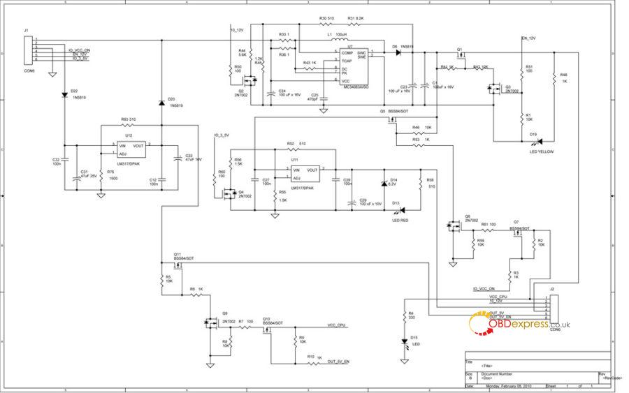
http://www.obdexpress.co.uk/upload/service/20042115874520694006.pdf
R2-750R___uart_mbus_bdm
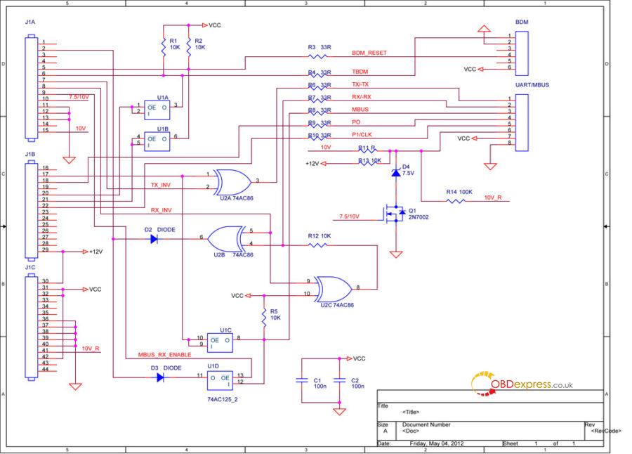
http://www.obdexpress.co.uk/upload/service/20042115874520701297.pdf
Enjoy!
V84 Iprog+ with 7 adapters:
http://www.obdexpress.co.uk/wholesale/iprog-pro-with-7-adapters.html
Posted by: OBDexpress.co.uk at
07:34 AM
| No Comments
| Add Comment
Post contains 36 words, total size 3 kb.
April 20, 2020
Car model:GM Corvette C6
Device:VXDIAG Nano with USB cable not Wifi
Error:
Won’t connect to the car
Can’t get the licensee to load
How to solve?
Problem with WI-Fi unit, is that the Nano needs to be connected to the car so the nano has power to begin with. Also, OBDII port needs to be powered up, so on a C5, car has to be in run postion before the OBDII has power itself.
Because of that, even on the Wifi unit I have, I still use it with a cable so the laptop powers up the nano to begin with, and don’t have to worry about the OBDII power instead..
When you load it make sure you run the installed updates from tech2win.
You also cant use a 64bit OS system it has to to be a 32bit device. The newer units (if bought on amazon) are 32bit and cant run from a Vm image that is 32bit OS.
I had the same issue. I pulled out a old laptop and installed win10 32bit and ran the updated add-ons from tech2win.
Load VX manager first, plug in the Nano, and get it working in VX manager. Hence click on firmware icon to update the firmware, then click on licence icon to install the licenses.
Now with the VX manager open and the nano plugged in, now load that auto install.exe of Tech2 win to load it from the White disc that came with the Nano to your machine. Hence the autoinstall.exe will need to over ride some VX manager files when it installs, so VX manager has to be open with the Nano connected/being seen in VX manager when you load tech2 win auto install from the disc. Installing tech2 win, with VX manager not open and the nano not plugged into the machine will end up with install problems every time with Win 64bit system.
Lastly, if you are loading in the Newer VX manager, you have to go in and install the needed programs from inside VX manager (no long load into VX manger from the white disc). So Tech2, GDS2 and SPS have to be installed from within VX manager. If you check in VX manager and these are loaded already, uninstall and reload them from VX manager again if you are having problems. When you have done these three reloads, go back in the licence tab in VX manager and make sure you are showing licences for all three of these. If not, then go back to the main page and click on the licence ion to update the licences on the refreshed installed. I bring this up, since if you are using the last right hand top tab in VX manager to download the lastest VX manager, you will have to install Tech2win/gds2/SPS from within VX manager (will still use the white disc to install Tech2win to the laptop to get the the desk top icon.
Now the glitch with A/C Delco TBS.
If you are using the older VX manager and older firmware on the Nano, when you get the screen to install the BoschTech2 win driver and GDS2 in TBS (will be a pop up screen), you want to skip these installs each time you use TBS.
If you are using the latest VX manager and latest Nano firmware, then you want to install these two Bosch drivers from TBS instead.
Trust is, for TBS now, you want to be using the latest VX manager and firmware. When you load the two Bosch drivers, it going to to load another program that is needed to get the Nano to work (TBS changed about a year ago, and its this third driver that loads with the Bosch drivers that is needed to get the Nano to work with the system.
Source:http://www.obdexpress.co.uk/service/how-to-solve-vxdiag-nano-gm-error.html
Posted by: OBDexpress.co.uk at
09:12 AM
| No Comments
| Add Comment
Post contains 650 words, total size 4 kb.
April 17, 2020
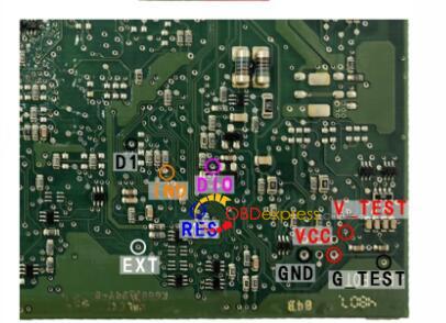
Question:Hey on BMW cas 2 to write data can I solder directly to the board since I don’t have adapter?
My purpose is to renew cas.
Look the image 1 ofACDPoption and the pinout:
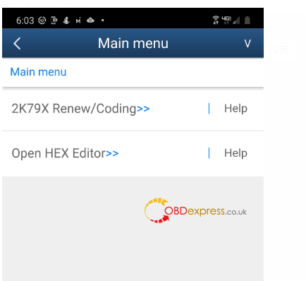
Yanhua ACDP chief engineer replied:
You can read the CAS2 data by insertingACDP MINIto the car’s OBD2 port.
If the CAS2 is dismantled, please buy one extra ACDP module 1 inside there is one BDM-ICP adapter, use it to read out the CAS2 data and to renew.
Image 3: yanhua mini acdp module 1
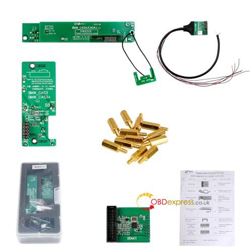
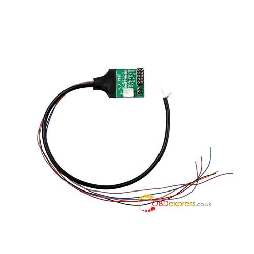
Image 4: BDM-ICP adapter
Related article:
How to use ACDP to renew the eeprom data of CAS1-CAS4?
Posted by: OBDexpress.co.uk at
03:45 AM
| No Comments
| Add Comment
Post contains 114 words, total size 3 kb.
April 15, 2020
Car model and year: 2015 Ford F550
Purpose:
I replaced the calipers/pads/rotors on all 4 wheels and tried to bleed the system (didn't go so well).
Front brakes seems to work fine -- press on the pedal, pads squeeze.
Rear brakes aren't getting any brake fluid.
Disconnected the brake line before the splitter on the rear axle -- no brake fluid comes out when stepping on brake.
I thought maybe the line was clogged or broken (nothing dripping). Disconnected the rear brake line as it comes out of the ABS controller and blew it clear (seems okay).
Stepped on the brake pedal and fluid comes out of the port on the abs (not very high pressure, but comes out).
Reconnected the line at the ABS block and still no fluid comes out at the rear of the line before it connects to the splitter.
Disconnected the output of the brake master cylinder and pressed on the brake pedal and plenty of pressure there.
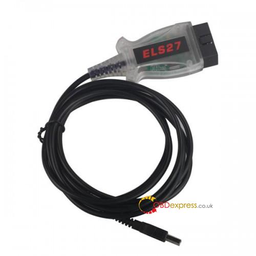
Using experience:
- Forscan + ELM32/ODB2 USB cable: failed
To bleed the system you need to have a laptop, Forscan and an ODB2 cable. This will allow you to open the ABS valves for the front and rear to get rid of any trapped air. The idea is to have the ABS system open when you are bleeding it.
I ordered an ELM32/ODB2 USB cable and downloaded Forscan
- Ford VCM2: Confirmed
Distinguished Diesel has given you the correct information. I'm also certain there are no service procedures available in ForScan to ABS bleed the brakes on your 2015. Many have asked ForScan for this functionality to be added for the 11-16 super duties but they have not implemented it yet.
There are other tools such as Autel MaxiCheck Pro that have this functionality or alternatively you can take it to a shop which has IDS or the new VCM2 Ford tools to do the service bleed. I have a Motive Products pressure bleeder that attaches to the master cylinder which has been great for my needs.
Advice:
Blowing compressed air into an ABS unit is not something I would ever do, the unit can handle over 2,000psi, but the air is the enemy.
Once vehicles had three or four-channel ABS, Superdutys MY2000, there was no need to incorporate any manual proportioning valve. The proportioning of the rear brakes is done dynamically when the ABS cannot control the wheel skid effectively, which is a minor incidence. Rather than repetitively opening and closing the valving, dumping pressure into the accumulator and reapplying pressure with the pump, it just dumps and holds a reduced amount. There is no special valving for reduced pressure in the sense of the older proportioning valves, pre MY2000.
Any air in an ABS unit can be a devil to get out. If the air has filled the accumulator and surrounds the valves, it can exceed the volume capability of a single pedal to floor pump, releasing the brake pedal just pulls the fluid back into the master, creating a never-ending story. It's usually just bad if you have done a multi-caliper brake job and let the master cylinder reservoir drain, and can take the specialized software to get the ABS to become active, or the very long process of bleeding as best as one can, causing low-speed wheel skids on dirt, then re-bleeding over and over to fully clear the brake hydraulics over several hours. Blowing air into the ABS becomes medieval.
Pulling the fuse is the equivalent of the key-off. It does nothing.
Source:http://blog.obdexpress.co.uk/2020/04/14/2015-f550-abs-service-bleed-with-vcmii/
Posted by: OBDexpress.co.uk at
03:08 AM
| No Comments
| Add Comment
Post contains 600 words, total size 5 kb.
April 13, 2020
This article is available with the working solution of V2020.03 Xentry error: The data are faulty and the software will upgrade automatically and then Xentry doesn't work.
Error 1: V2020.03 Xentry error "The data are faulty".
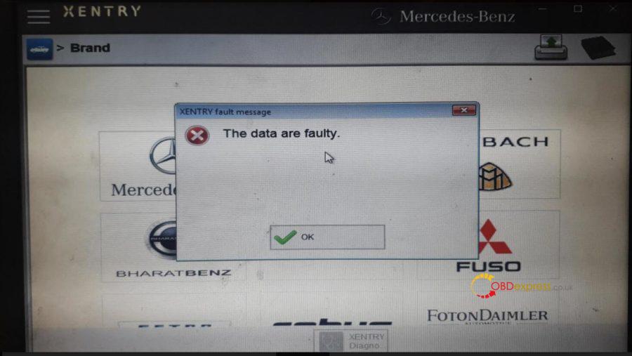
Solution:
Step 1. Pleasedownloadthesoftwarehere:
https://share.weiyun.com/5uIxwgI
password:eswr9a
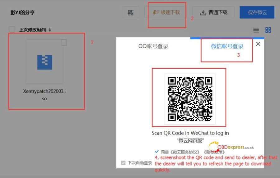
Step 2. follow the video to operate:
Step 3: Reboot the computer, then to run Xentry.
The above solution applies to:
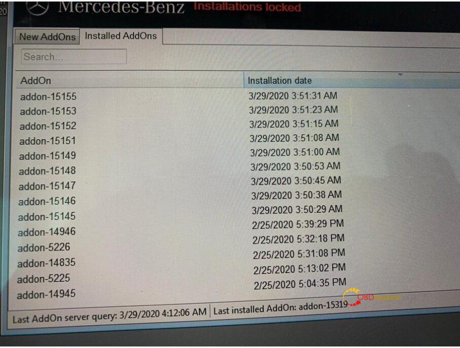
Error 2: The user didn't do nothing but the software upgrade automatically, and Xentry doesn't work.
Solution:
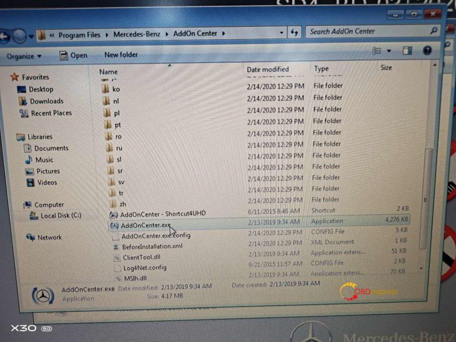
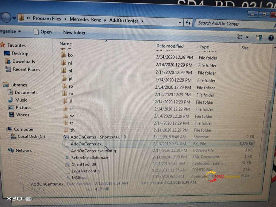
Go to program files -> Mercedes-Benz->AddOn Center, rename "AddOnCenter.exe" as "AddOnCenter.ex_", restart the computer, then the Xentry will not upgrade automatically.
Good luck!
OBDexpress.co.uk Office Blog all rights reserved How to fix V2020.03 Xentry error "The data are faultyâ€
Posted by: OBDexpress.co.uk at
07:19 AM
| No Comments
| Add Comment
Post contains 138 words, total size 4 kb.
April 10, 2020
IDS V177 is tested working fine with Ford VCM2 clone, this post is available with the newest IDS software new features, free download links and how to install.
- IDS V177 Free download + Installation Guide
Step 1: Download Diagnostic Software, then Install Diagnostic Software:
IDS 117 Full
www.fordservicecontent.com/Ford_Content/IDS/IDS-117.01_Full.exe
FDRS 23.5.7
www.fordservicecontent.com/Ford_Content/IDS/FDRS/FDRS_23.5.7.exe
Step 2: Download VCI Software, then Install VCI Software:
VCI Software 1.0.0.7
www.fordservicecontent.com/Ford_Content/IDS/VCI_Software/VCI_Software_1.0.0.7.exe
Step 3: Download Diagnostic Software Updates (if available)
Then Run Diagnostic Software Updates:
Update IDS 117.04
www.fordservicecontent.com/Ford_Content/IDS/SoftwareUpdates/IDS-117.04.exe
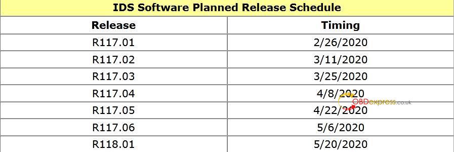
See IDS Update Release Dates below:
Step 4: Download VMS
Then Install VMS
(Optional - VCMM Users Only)
VMS v1.1.1034.0
Click here for VMS Manual
After Installing: Diagnostic Software Updates will pop up on Mondays and Thursdays when available.
- VCI firmware what's new - contain details on this new software.
IMPORTANT: Changes to VCM II and VCMM
VCM II & VCMM Device Software ("VCI Softwareâ€)
VCI Software
- Previously, installing IDS or FDRS would install everything that is needed in order to use a VCM II/VCMM with any of the Ford diagnostic software (IDS, FDRS & VMS).There is now a new package separate from
- IDS and FDRS, called VCI Software.
- This VCI Software package WILL NEED to be downloaded in order to use your VCM II or VCMM, regardless of whether this is the first time you have downloaded IDS/FDRS.
- This will improve download and installation time, as previously you were downloading and installing these components with BOTH IDS and FDRS.
- You WILL NOT need to download and install this package every release, only when there is an update to the loaded code on the device.
VCI Launcher
When launching the VCI Manager, you will be prompted to select which device (VCM II or VCMM) you intend to use.
Only the devices of the selected type will appear in the VCI Manager. If you wish to switch device type, you will have to close the VCI Manager and select the other device.
Note: If the device is already connected via USB, you will bypass the selection screen.
Figure 1: The VCI Launcher desktop icon
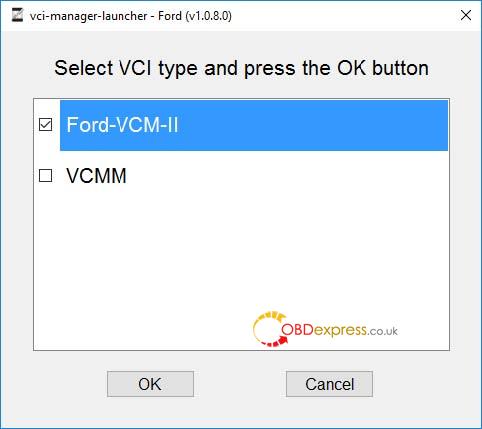
Figure 2: The main screen of the VCI Launcher
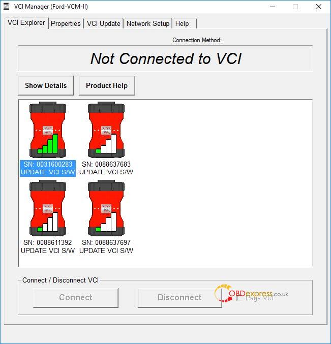
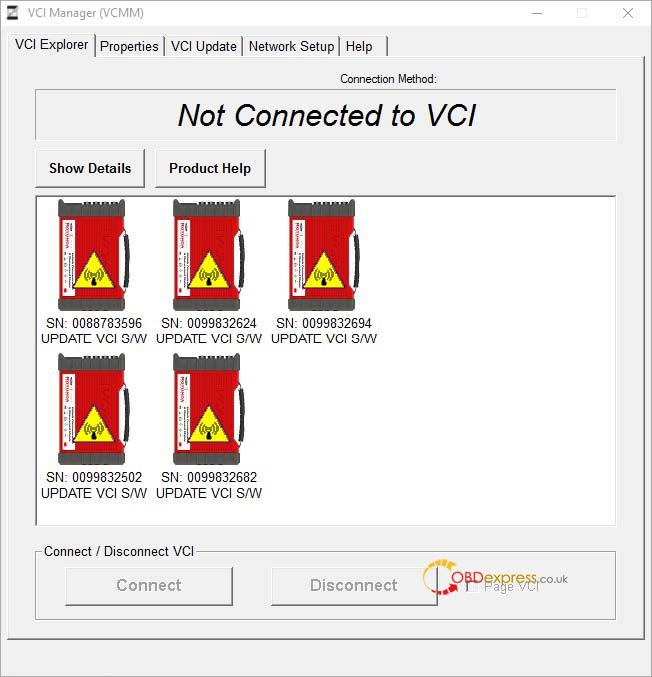
Figure 3: A side-by-side comparison showing the VCM II Manger and the VCMM Manager
Changes to IDS
- IDS now requires you to select your device type at the launch of IDS.
- If you wish to switch devices while in IDS, you need to navigate to what was previously the Wireless device manager (the green arrows in the upper right hand corner), select the button at the bottom left which says "VCI Type†and select which device you wish to use. You can do this at any time while in the IDS tool.
- Note: It is recommended if you previously pinned IDS to the task bar, that you unpin it in R115, and then re-pin it while on the device selection screen.
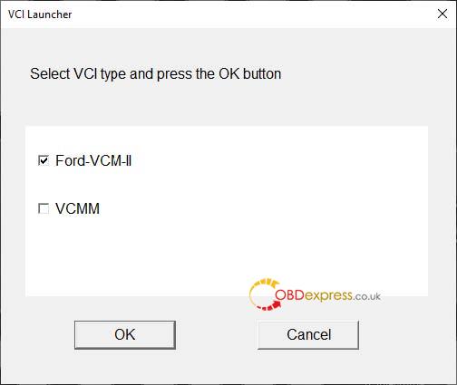
Figure 4: The device selection screen when launching IDS.
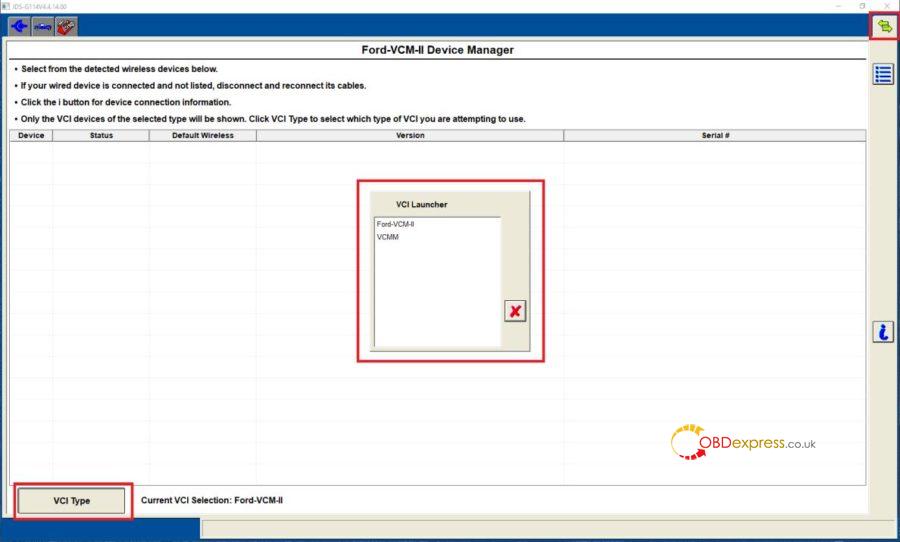
Figure 5: The new device manager screen. Note the icon in the top right, the VCI Type button in the bottom left, and the VCI Launcher selection window.
VCI Software Uninstaller
- There is now a new component included in the VCI Software package called VCI Software Uninstaller.
- This gives you the ability to uninstall all Ford Diagnostic components (IDS, FDRS, VMS, CFR, and VCI Software) from one central location, rather than having to uninstall each component individually.
- This uninstaller can be accessed by going to Startïƒ Ford Motor Companyïƒ VCI Software Uninstaller. After following the prompts, you can select which software applications you wish to uninstall.
- Note: If you are removing all components, it is recommended you select "Remove Uninstaller Data†to remove successfully all Ford components from the PC.
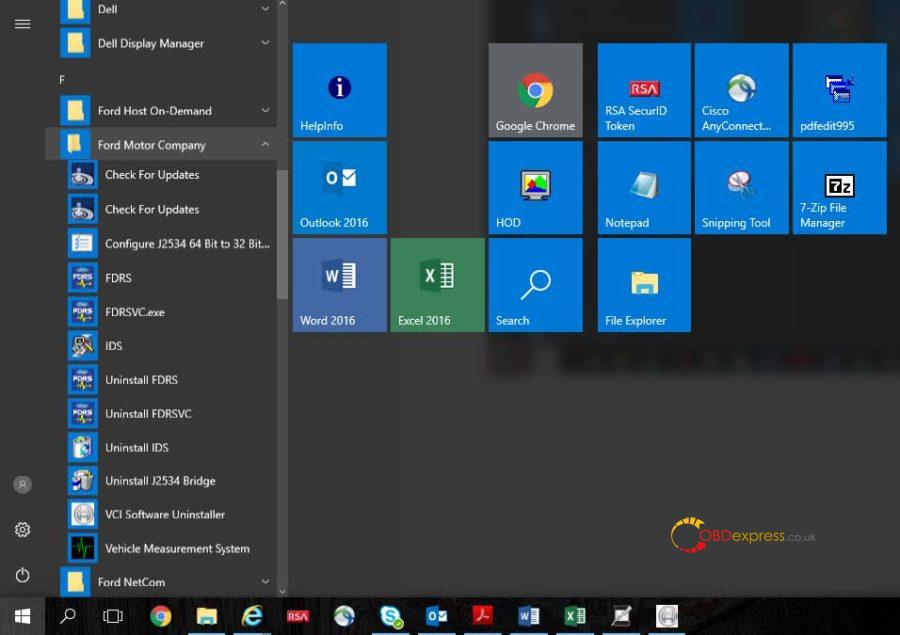
Figure 6: The location of the VCI Software Uninstaller
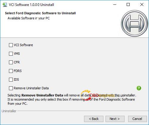
Figure 7: The main screen of the VCI Software Uninstaller
Best Ford VCMII with IDS V177 source:
http://www.obdexpress.co.uk/wholesale/ford-vcm-ii-diagnostic-tool-wifi-wireless-2.html
OBDexpress.co.uk Office Blogall rights reservedFree Download & Install IDS V177 Ford VCM2
Posted by: OBDexpress.co.uk at
09:16 AM
| No Comments
| Add Comment
Post contains 659 words, total size 10 kb.
April 02, 2020
Shared ISTA 4.22.3x update files.
https://mega.nz/#F!0JQGkC5L!iaTWcRL1YwNaw97f2ESkbg
Filelist:
507M BMW_ISPI_ISTA-APP_4.22.32.19941.msi
1.8G BMW_ISPI_ISTA-BLP_4.22.31.istapackage
391M BMW_ISPI_ISTA-DATA_DELTA_4.22.30.istapackage
2.4M BMW_ISPI_ISTA-DATA_DELTA_de-DE_4.22.30.istapackage
2.4M BMW_ISPI_ISTA-DATA_DELTA_en-GB_4.22.30.istapackage
28K BMW_ISPI_ISTA-META_4.22.32.xml
4.0K BMW_ISPI_ISTA-META_SDP_4.22.31b.xml
276M BMW_ISPI_ISTA_DELTA-SDP_4.22.30.istapackage
602M BMW_ISPI_ISTA_DELTA-SDP_4.22.31.istapackage
Here is the ISTA4.22.3x I-LEVEL+OVERVIEW.
Extracted from 4.22.3x update files.
Here are the Release_Notes_ISTA_Programming-P3.67.1_4.22.3:
Release_Notes_ISTA_Programming-P3.67.1_4.22.3_de-DE.pdf
Release_Notes_ISTA_Programming-P3.67.1_4.22.3_en-GB.pdf
Credits to @ lynxbmw and @ ingmv for their contribution.
ISTA 4.22.3x compatible hardware:
To be upgrading...
Posted by: OBDexpress.co.uk at
02:33 AM
| No Comments
| Add Comment
Post contains 72 words, total size 2 kb.
March 31, 2020
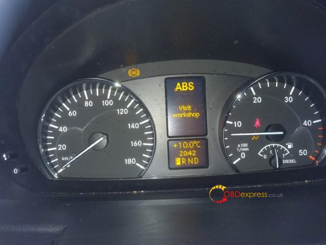
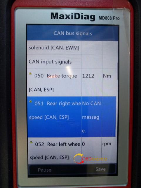
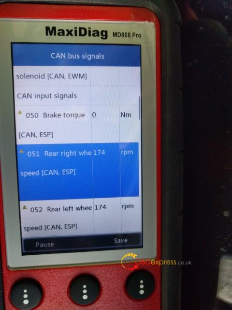
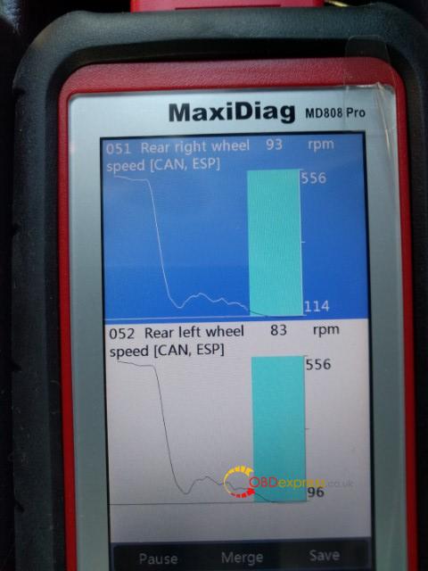
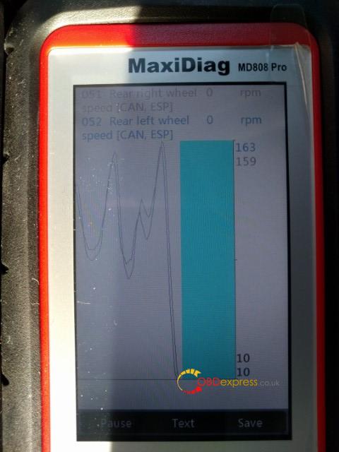
Car model: 2014 Benz 906.155
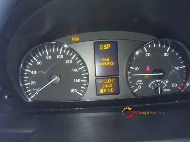
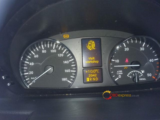
Symptom: Dash lit up with ABS, ESP, and traction warnings
Showing intermittent inability to get wheel speed from right rear wheel speed sensor. Looks like DTC is D40C.
Code scanner to use: Autel Maxidiag MD808 PRO
Test reports:
So far the MD808P has been very helpful.
Some specific notes:
- Creating an account on Autel, registering the scanner, and downloading scan updates were all incredibly easy.
- The unit uses a standard micro-sd, which can be removed and updated seperate from the unit
- Alternately, the unit can be updated via a USB cable.
- Power is supplied via either the USB or OBD cable, there are not batteries.
- Feel is generally good. Lighter than I expected, but quite reasonable.
- The screen is non-touch, but is clear, and easy to read.
- Currently only covers pre 2016 sprinters.
Warning ABS:
Warning ESP:
Warning Misc:
DTC D40C:

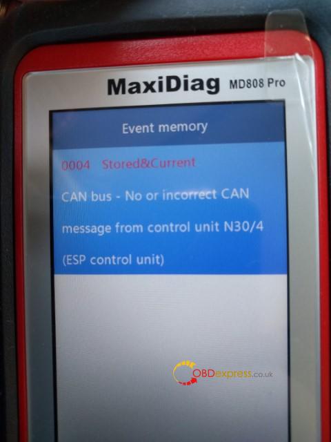
get wheel speed from right rear wheel speed sensor, DTC is D40C:
Autel MD808 Pro Sprinter Coverage:
Newest Sprinter coverage + the other coverage:

https://www.autel.com/vehicle-coverage/coverage2
Enjoy!
Posted by: OBDexpress.co.uk at
05:49 AM
| No Comments
| Add Comment
Post contains 184 words, total size 7 kb.
March 25, 2020
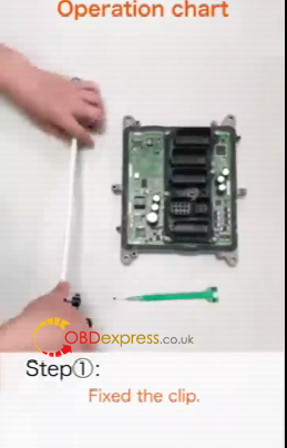
How connect Single Probe Solderless Connector with the ECU?
1.video demo:
https://youtu.be/nTsf7xiQe2A
2.Step-by-step:
Step 1. Fix the chip.
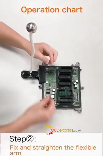
Step 2. Fix and straighten the flexible arm.
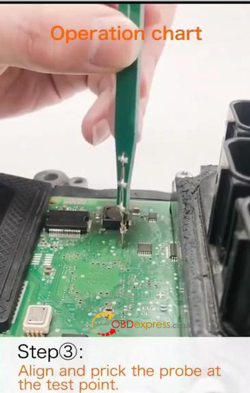
Step 3. Align and prick the probe at the test point.
Use the PCB probe board to align the through -hole test point or solder pad test point.
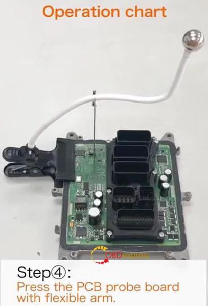
Step 4. Press the PCB probe board with flexible arm.
Note that the angle between the flexible arm and the PCB probe board should be kept at 90°.
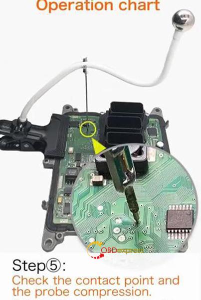
Step 5. Check the contact point and the probe compression.
Adjust the inclination of flexible arm according to the length of the probe compression.
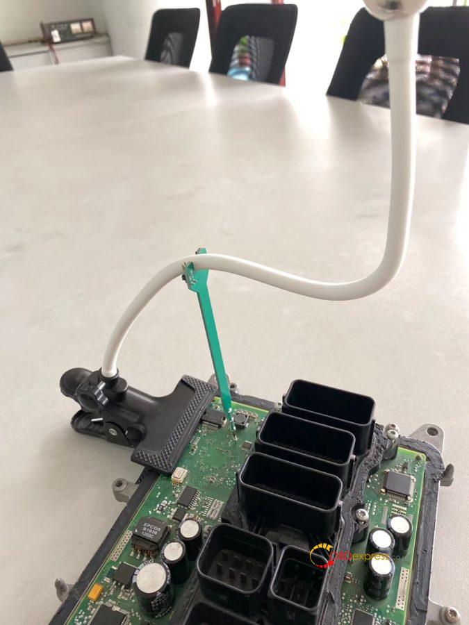
Single Probe Solderless Connector.
No soldering, No risk!
What it can do:
- Provide solderless connecting during in-circuit programming (ICP) testing.
- Connect the Boot point when opening DME shell to read ISN code.
Compatible devices:
Yanhua Mini ACDP: tested
The other devices: Yes

(Image: How connecting with manhua ACDP)
3 Pros of single probe solderless connector:
- Excellent versatility: compared with the traditional ECU worktable, it is compact in size, easy to carry, has multiple fixing modes, more suitable for outdoor or indoor work.
- Simple and high efficiency operation: the connection can be simply completed by pulling and pressing.
- Modular design: free switch among single point connection, multi-point connection and combination connection.
Yanhua Single Probe Solderless Connector best price offers here:
http://www.obdexpress.co.uk/wholesale/yanhua-singe-probe-solderless-connector.html

Posted by: OBDexpress.co.uk at
10:07 AM
| No Comments
| Add Comment
Post contains 233 words, total size 5 kb.
March 23, 2020
Car model and year:
2002 - 2005 Porsche 996 that had the OBC but not cruise control.
Pre 2002 the wiring is very different t…it needs to be fed to the DME in the rear of the car rather than the instrument cluster (It’s MY2001 onwards I believe).
Time to use:
From start to finish it took me around 3 hours.
This included reading my instructions, re-reading my instructions, taking pictures and taking my time. I also haven’t factored in the time for coding the DME once the work has been completed.
The list below is a high level grouping of what I did, and the order I did it.
- Find and buy all the parts…know exactly what you’re doing with each
- Remove the instrument cluster
- Remove the steering wheel
- Remove the old stalk unit
- Clean the now-visible parts of the dashboard (you find a lot of dust and dirt)
- Put together the wiring
- Fit the new stalk unit
- Wire up the new stalk unit to the instrument cluster
- Re-fit the steering wheel
- Re-fit the instrument cluster
- Connecting the new stalk unit to the fuse-box
- Coding the DME
Step 1 – What you’ll need to buy
All parts and prices were correct as of September 2016 and were purchased from OPC Bournemouth and Breeze VW Poole.
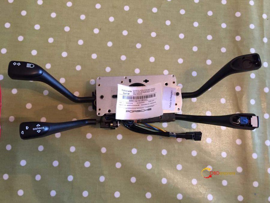
Part Name: 4-Stalk cluster (Indicators, Wipers, OBC, Cruise)
Part Number: 996-613-219-10 EWC
Quantity: 1
Price: £202 (£168.97 + VAT)
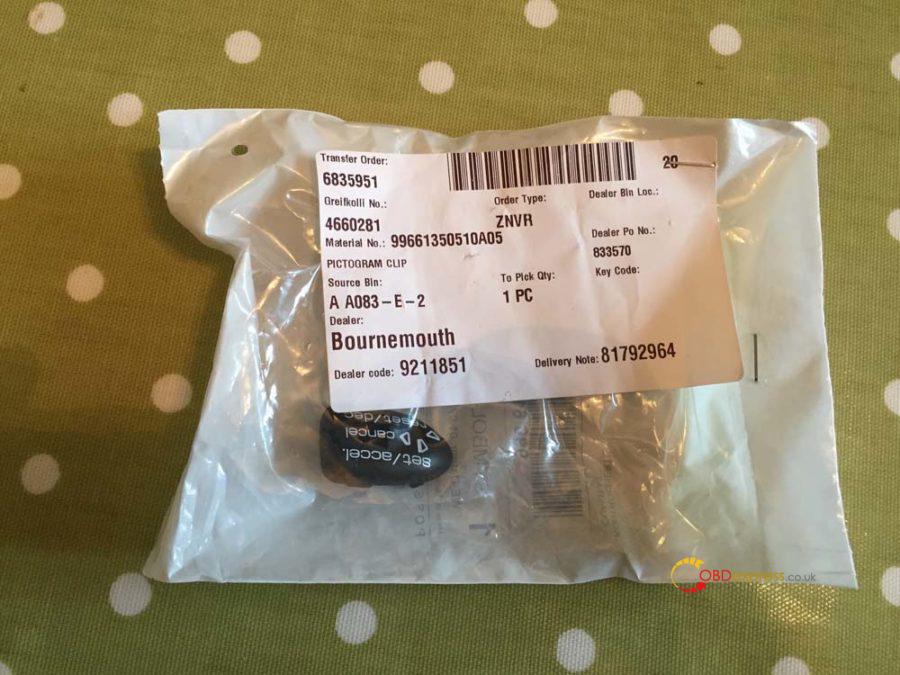
Part Name: Cruise control cap for stalk cluster
Part Number: 9
Quantity: 1
Price: £4.70
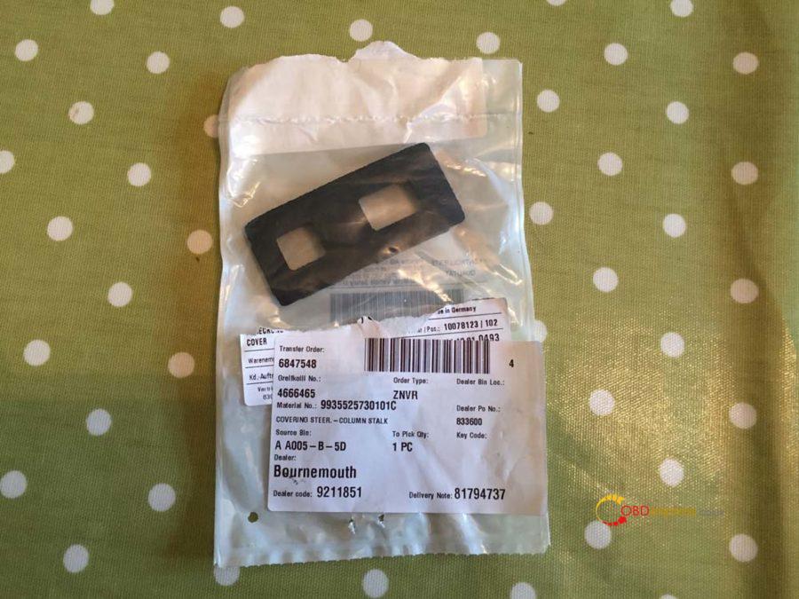
Part Name: Wiper/Cruise stalk cluster grommet
Part Number: 9
Quantity: 1
Price: £9.97
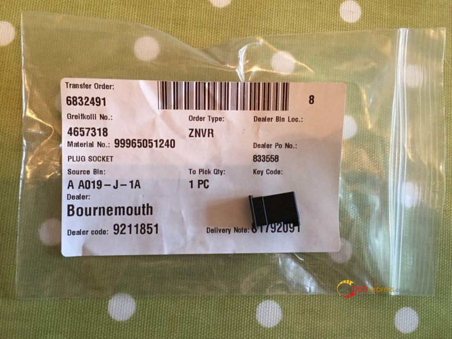
Part Name: Cruise stalk cluster wiring connector
Part Number: 999-650-512-40
Quantity: 1
Price: £0.07p
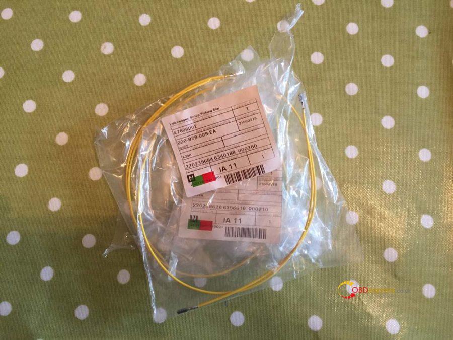
Part Name: VW repair wires (Yup from VW)
Part Number: 000-979-009 EA
Quantity: 4
Price: £20.16 (£5.04 each)
Part Name: 22-gauge wire
Quantity: 1m
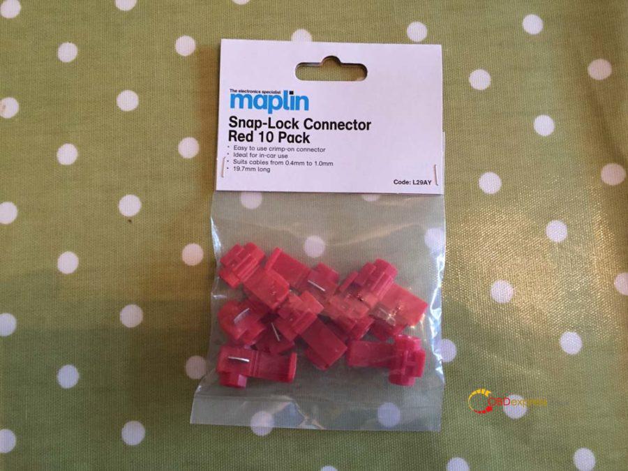
Part Name: Snap-Lock connectors
Quantity: 2
Price: £2.39 for 10 from Maplin
DME coding by OPC: £66
Total price for the project: £305.29 (£239.29 if you can do the coding yourself)
You’ll need to have the following tools:
- 24mm socket
- T30 torx
- T20 torx
- T10 torx
- Philips screwdriver
- Blunt knife
- Wire cutters
[So here’s the picture of all the part’s (excluding the 1m wire)
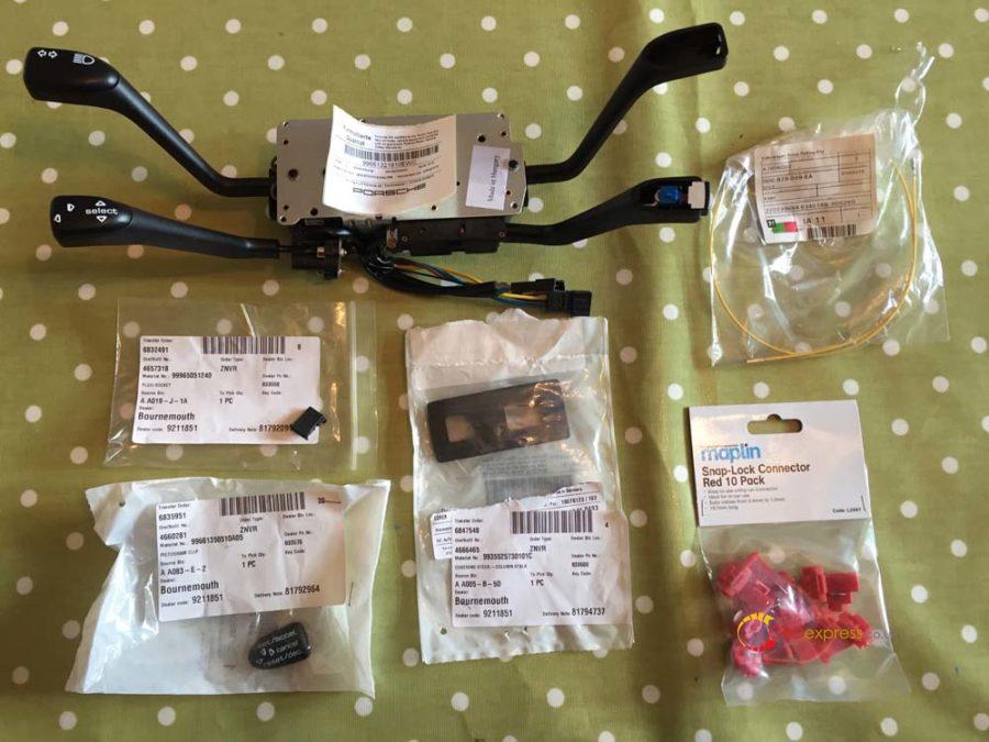
And here’s a close up of each part:
The 4-Stalk cluster (Indicators, Wipers, OBC, Cruise). You’ll notice it doesn’t come with the cruise cap or the wiper cap so you can transfer the wiper crap from your old stalk cluster.
Cruise control cap for stalk cluster.
Wiper/Cruise stalk cluster grommet. If you don’t want to buy the grommet, when you take the old one out you’ll see there is a square mark you can cut along…saves a few quid.
Cruise stalk cluster wiring connector.
VW repair wires – They will generally have these in stock as they’re a fairly common part.
Snap-Lock connectors from Maplin.
Step 2 – Removal of the Instrument Cluster
Before you begin make sure you disconnect the battery and leave it at least 15-20 min to ensure the airbag’s have completely disengaged. Put the key in the ignition and turn it all the way but do not start the engine, then disconnect the battery. This will prevent the alarm from sounding. Leave the key in the ignition until you have finished and are ready to re-connect the battery. It’s also worth mentioning and may seem like common sense but leave the frunk open otherwise you lock yourself out of the battery and it’s a faff to get back in.
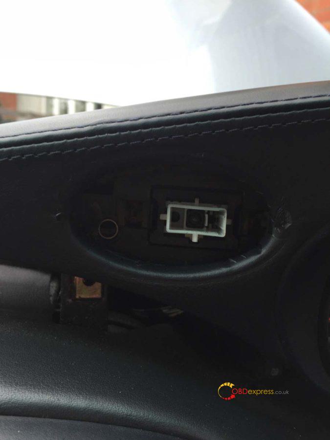
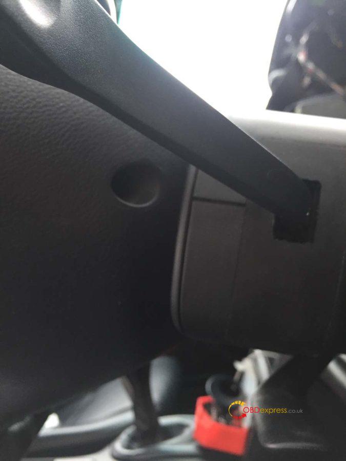
To remove the instrument cluster there are two torx screws you need to undo. One is behind the microphone on the right and the other is behind the hazard light on the left.
If you use a blunt knife (with a microfiber cloth under so you don’t damage the dash) you should be able to lift the microphone out and you’ll see the screw at the back. Don’t worry if the screw falls, there is enough stuff to stop it disappearing into the cluster. I believe these screws were the T20 torx screws.
Push the hazard light button in so it pops out and you can then pull the button out of its housing. Then you should be able to remove the button surround, there are two clips inside the surround you need to push in when pulling it out.
Once you’ve removed the hazard light and surround you’ll see the torx screw in the bottom left corner:
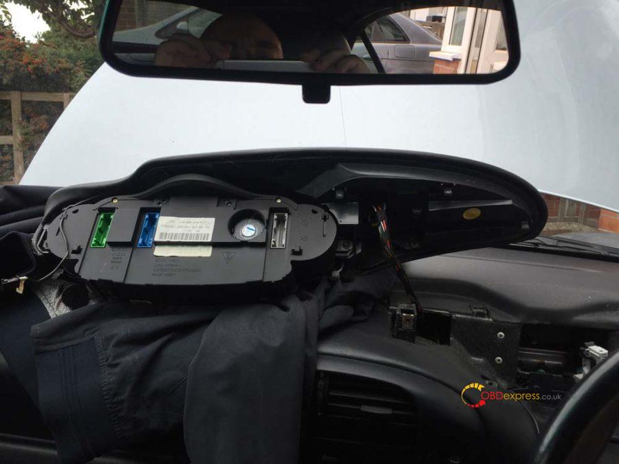
Once you’ve undone the two screws just lift the instrument cluster upwards. You may need to use a little force (not too much) and give it a slight wiggle. It’s also at this point you’ll find any missing parking tickets…I found a valet parking ticket for the Lanesborough hotel (from the cars previous owner unfortunately).
Once it’s free you’ll find 3 coloured plugs in the back, green, blue and gray. You’ll also find a connection for the hazard switch and the microphone. You only need to unplug the green, blue and gray connectors as well as the microphone…leave the hazard plug in.
Here you can see the green and blue cables and in-between them the microphone connector.
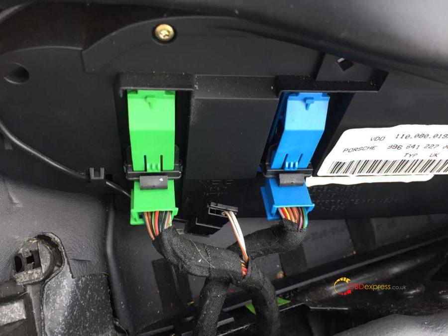
These disconnect by pushing in the clip in the middle and then sliding the black bar all the way to the top. Click the bar in place at the top and the connector will pop out.
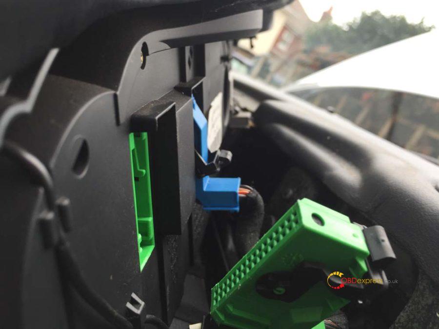
Put some cloths or sheets across the dash and swivel the instrument cluster across and out of the way.
The gray connector is the only one we’ll be working with.
Step 3 – Removal of the steering wheel
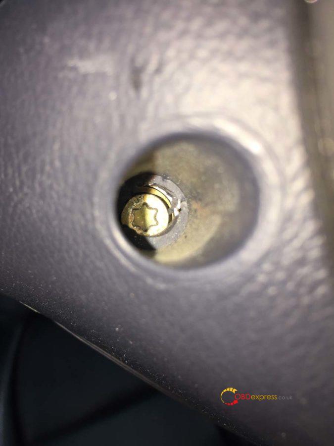
We firstly need to remove the center piece of the steering wheel, the airbag and horn. On the back of the wheel just in front of the stalks you’ll find two holes with spring-loaded screws. These are T30 torx screws and when undone should not come out.
You should be able to lift the air bag out carefully. At this point I rested it on my knee and with the blunt knife carefully lifted the yellow connector out. Place the airbag unit to one side with the Porsche crest facing upwards.
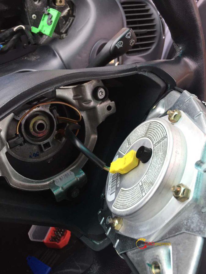
Disconnect the two spade connectors you’ll see on the next picture.
Draw a line with a marker pen down the center nut to mark its position. This is to make sure when you put it back together it goes back in the same place.
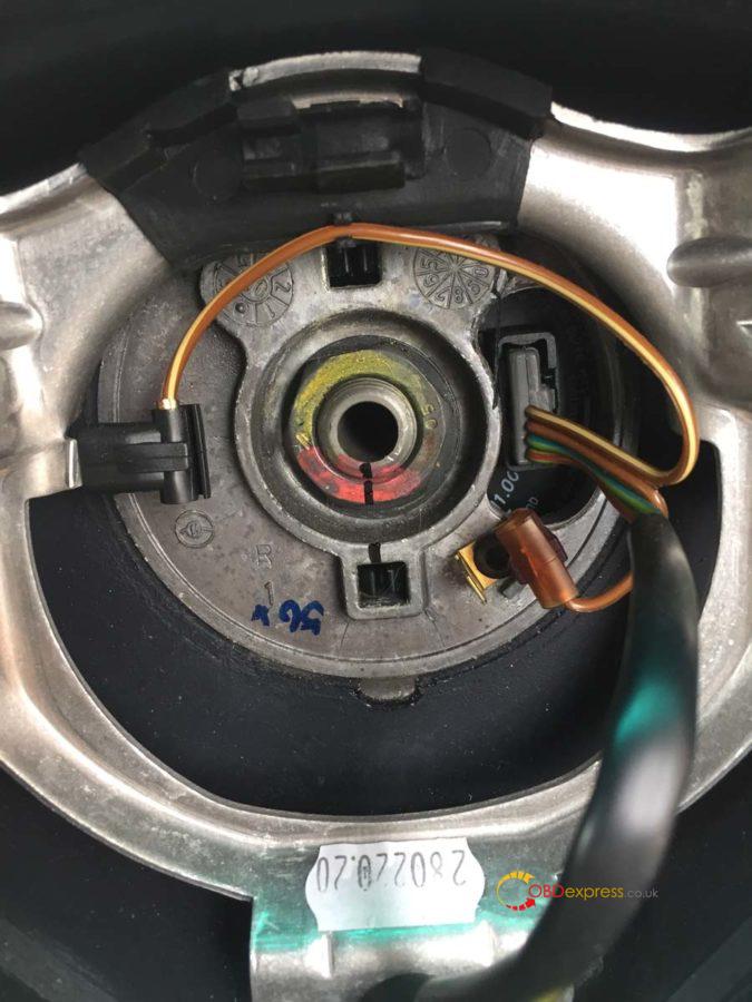
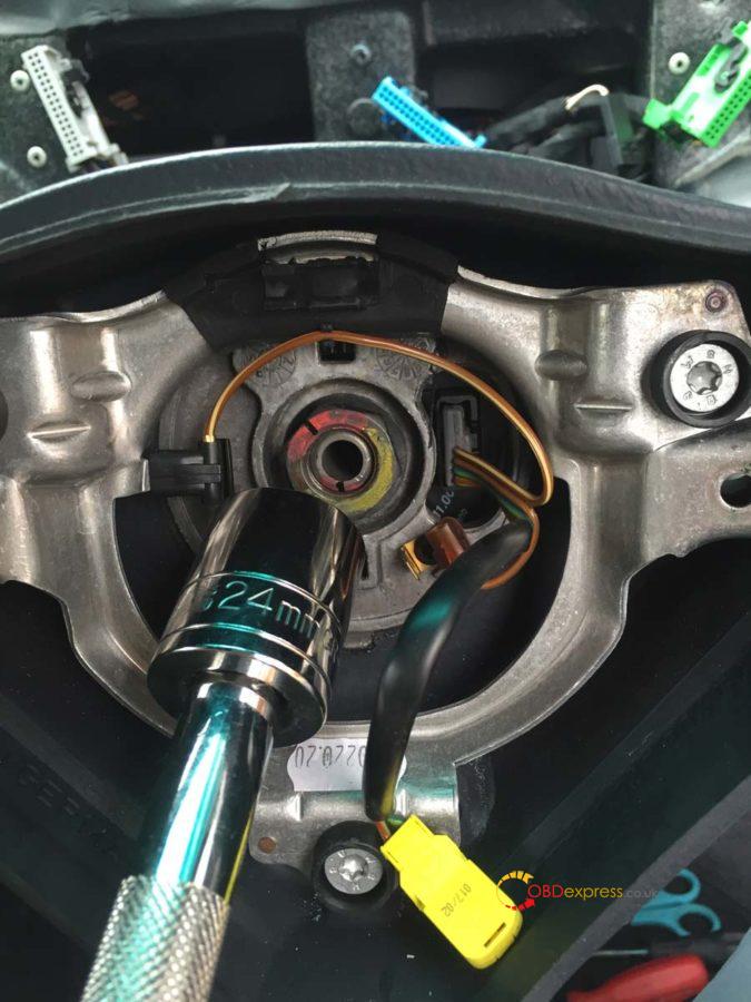
Using a 24mm socket undo the wheel nut. You will find the steering wheel wants to turn so carefully hold it in place with one hand whilst you undo it (You’ll notice at this point I hadn’t undone the two spade connectors).
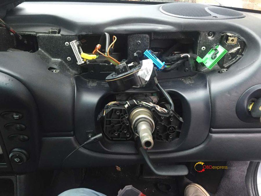
This should be the current state of your dash.
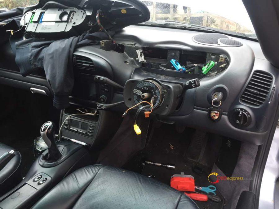
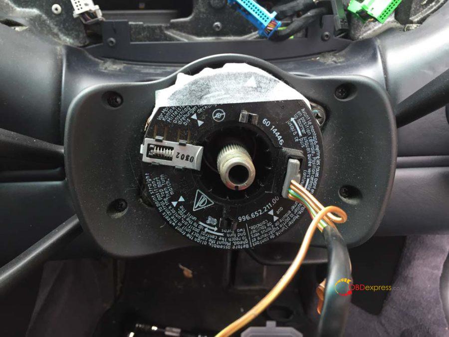
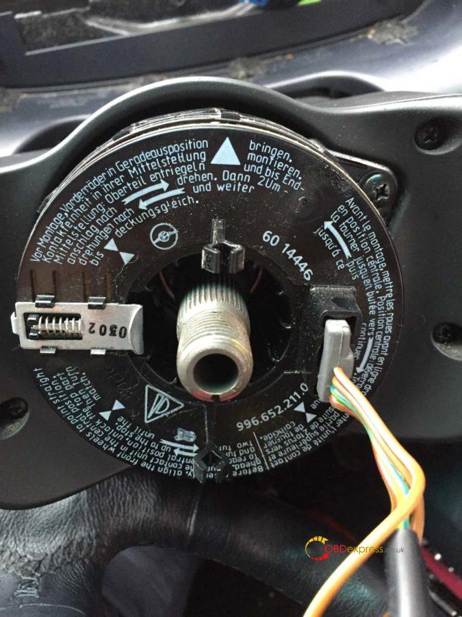
Tape the clock-spring connector unit to stop it moving around. Be careful of the two plastic prongs, if you snap these it’s an expensive part to replace. Undo the 4 screws and remove the faceplate. You can also undo the two screws securing the clock-spring connector unit at this point or wait until after removing the steering column panels.
Here’s a helpful video for removal of the steering wheel to make some of that a bit clearer (it’s not my video).
https://youtu.be/hux78ZoPcAI
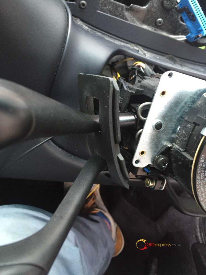
Step 4 – Removing the stalk cluster
Remove the two small T10 torx screws on either side of the steering column.
Lift the top away first and put it to one side.
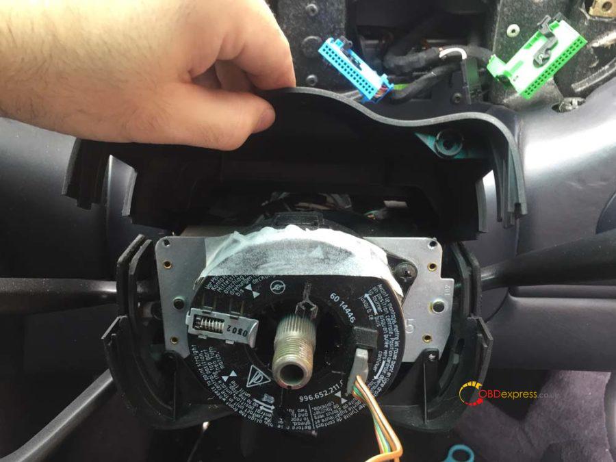
Now start to remove the rubber grommets that the indicator and wiper stalks feed through. You’ll more than likely need to move the indicator down and the OBC (if you have it) up to pull it off.
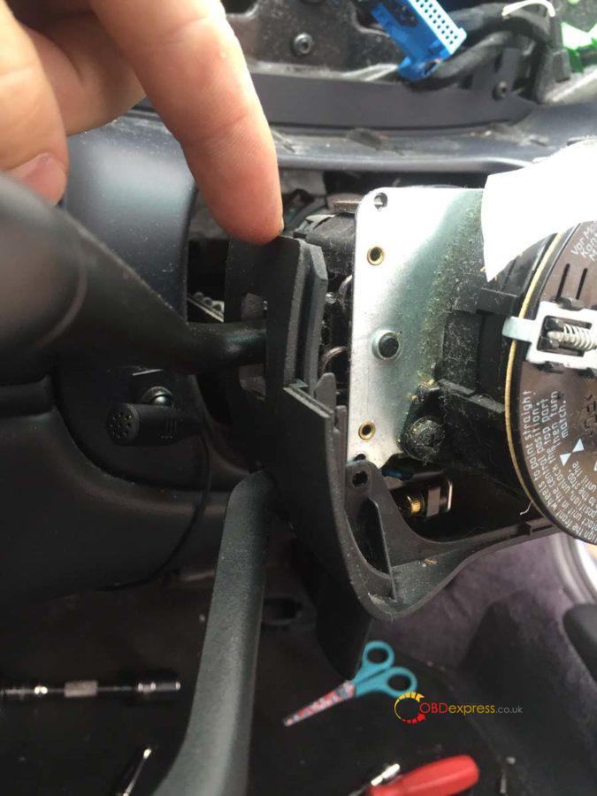
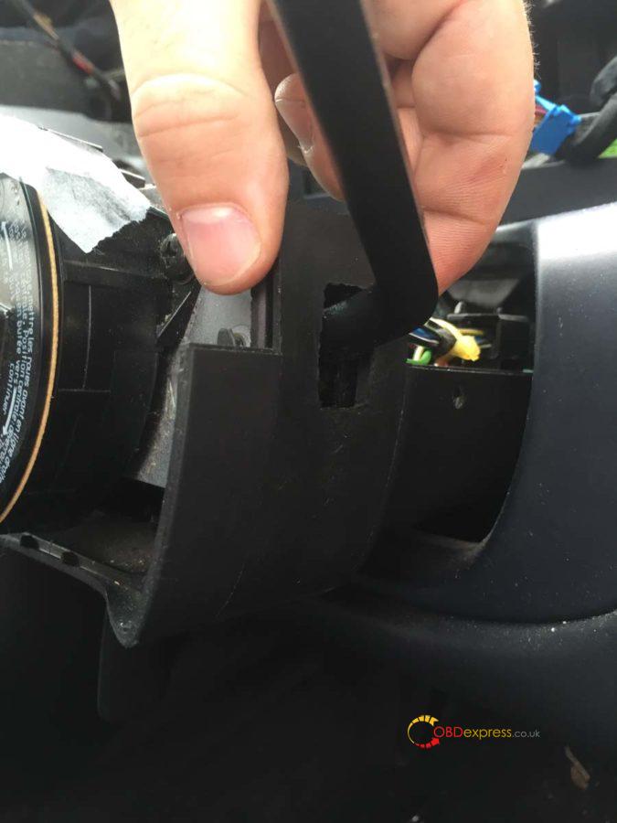
Once both grommets are off you can remove the lower panel.
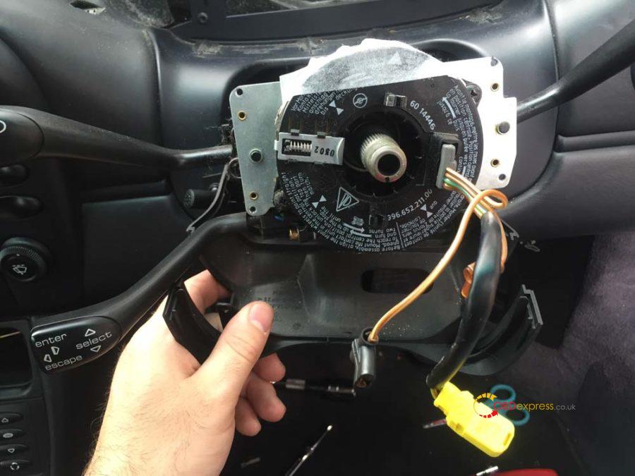
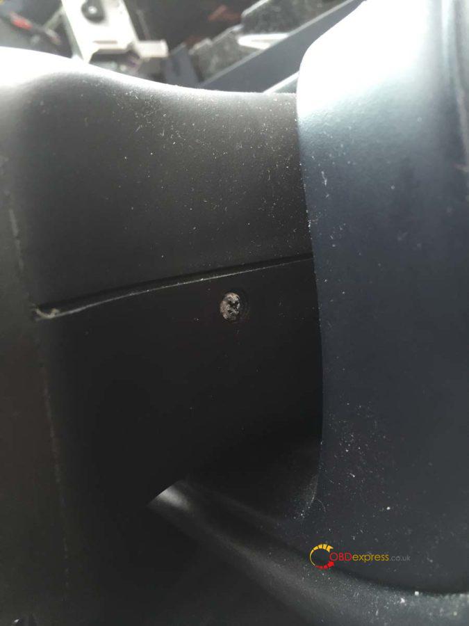
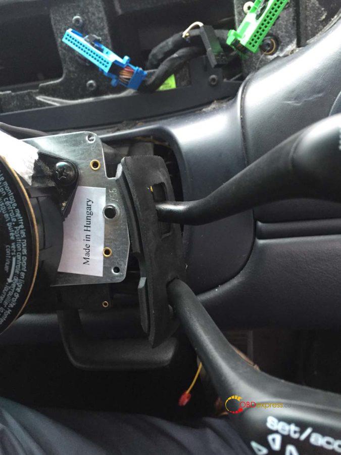
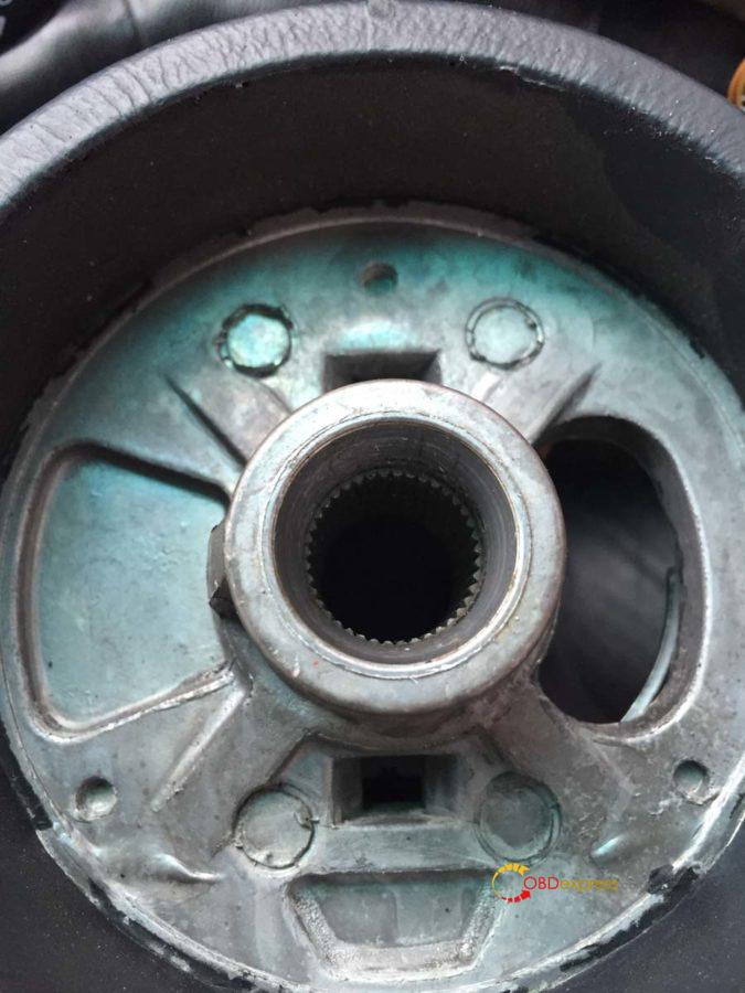
Measure the position of your current stalk cluster to the end of the steering shaft. It should be 55mm. Mark this position on the shaft as we’ll need to put the new stalk cluster at the same point. Now loosen the bolt you can see in the image below, don’t undo it fully.
Disconnect the two large connectors either side of the stalk cluster and then remove the stalk cluster from the steering shaft.
This is one of the large connectors.
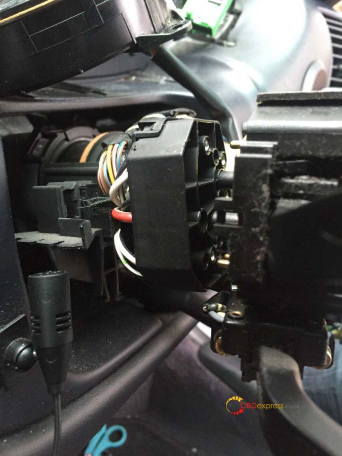
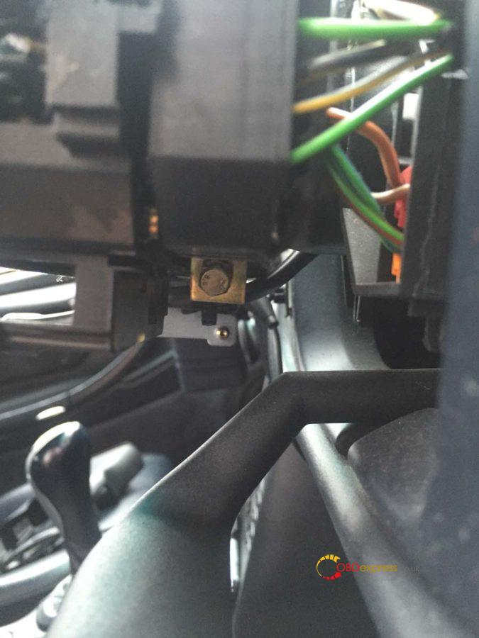
If you have the OBC you’ll find a smaller additional connector you need to undo. It may be housed in the small black clips you can see in the background of the image below.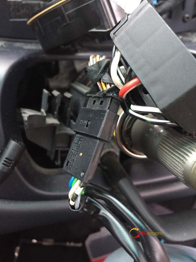
I found this clip a real pain to undo. Use your blunt knife to stick in and undo the latch (for reference in the image I pushed the knife down into this connector from the top and lifted it up slightly to free that tiny bit of plastic in the hole.
It was at this point I stopped for some tea and also gave the dash a good wipe down as it was very dusty.
Step 5 – Wire up and fit the new stalk cluster
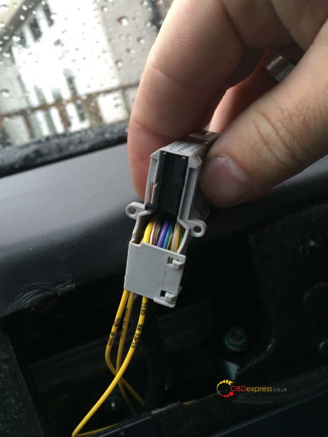
Take the 4 yellow VW repair wires and plug them all into the small 4 pin connector you bought. You’ll find the numbers 1 and 4 on one side of the connector indicating which is pin 1 and which is pin 4.
Using the snap-lock connectors, attach the yellow wire from pin 2 to the piece of 1m wire. This will need to be routed down to the fuse box which we’ll cover off in the last section.
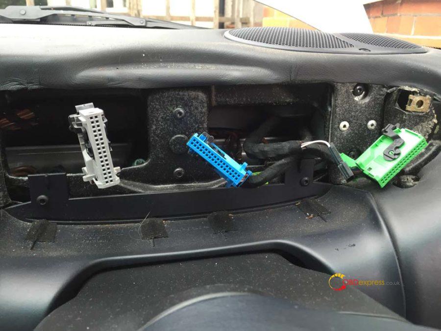
Pins 1, 3 and 4 will be plugged into the gray instrument cluster connector.
On the gray connector you’ll see a sort of door which is protecting the cables and keeping them tidy, undo this. On the side of the connector you’ll see a small latch that will allow the black bar the cables are plugged into to slide out. Remember which way you took it out as it must go back in that way.
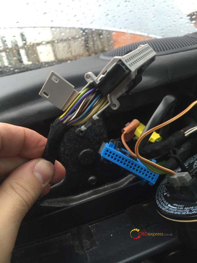
Like before you’ll find numbers at either end of this connector indicating the pin slots. This is a double decker so pins 1-16 are on the top and 17-32 are on the bottom.
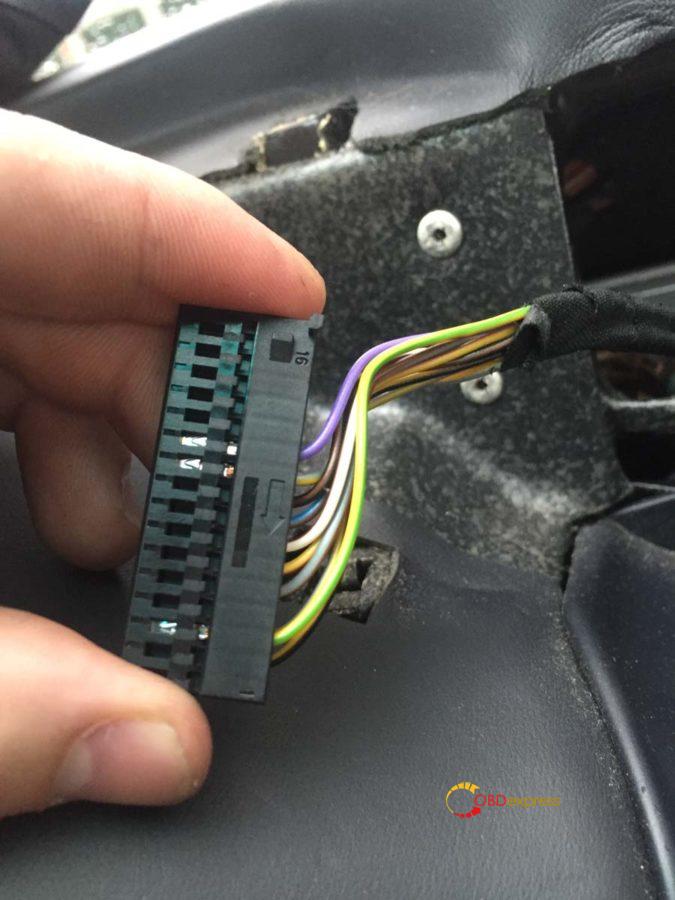
Feed the wire from pin 2 of the stalk cluster down the right side of the steering shaft and into the drivers footwell. You should be able to poke your hand up from underneath to help pull it through.
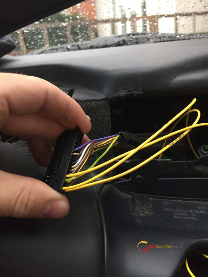
One at a time, feed the other remaining yellow wires from the stalk cluster through the left side of the steering shaft and up through the top slot of the dash (it should follow the same path as the gray connector). Connect the wires to the following slots on the gray connector:
Stalk cluster pin 1 > instrument cluster pin 17
Stalk cluster pin 3 > instrument cluster pin 4
Stalk cluster pin 4 > instrument cluster pin 1
So it should look like this:
Doing it one at a time means you should connect the correct cable to the correct slot.
Push the connector bar back in and close the wire door keeping the wires tidy.
Plug the cruise connector we’ve just wired up into the stalk cluster and also plug in the OBC 5 pin connector. Using some small cable ties, tie the wires together and tidy it up.
Place the two connectors in these slots to keep them secure. The OBC, if you have it, should have been in one of these already.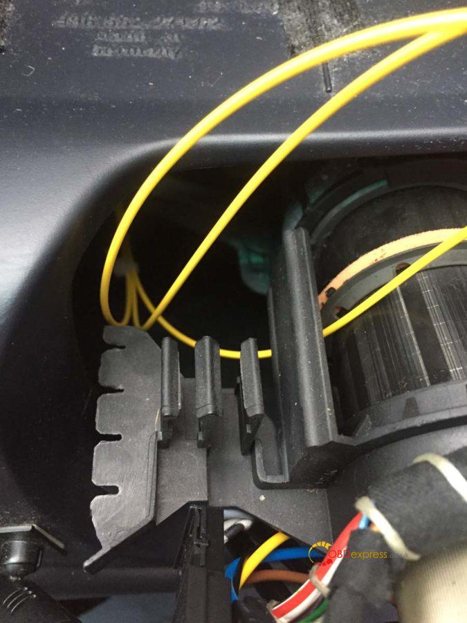
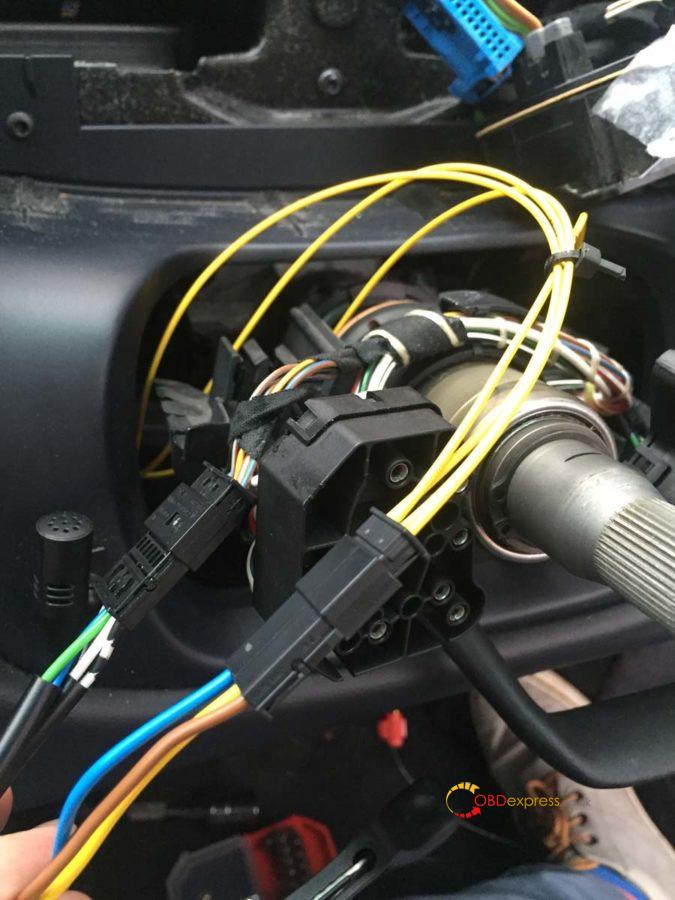
Step 6 – Fit the new stalk cluster
These steps are now basically the reverse of what we’ve done to get to this point. Slide the new stalk cluster onto the steering shaft and back to the same position as the old one (55mm from the end of the shaft). Tighten up the bolt from underneath when it is in position and straight.
Reconnect the large connectors at the back of the stalk cluster.
You can now slide on the rubber grommets. The left side is easier than the right as both the indicator and OBC stalks move to the center. Be careful with the cruise stalk as it doesn’t feel like it wants to move up for you to get the grommet on.
Reattach the clock-spring connector unit, the steering column panels and faceplate. You can now remove the tape holding the clock-spring connector unit.
Push on the steering wheel. The two plastic prongs on the clock-spring connector unit feed into two slots on the steering wheel.
This is the back of the steering wheel – the two slots top and bottom is what I referenced above.
Tighten up the nut to attach the steering wheel and tighten it so your marker pen is back in line. Plug in the two spade connectors and re-attach the airbag.
Now to re-attach the instrument cluster. Swivel it back around into position and re-attach the 3 coloured plugs plus the microphone cable. Push the plugs in and pull the black bar down to secure it in place. The cluster should slot back in without too much trouble, remember to tighten your screws and push your hazard button and trim back into place.
Everything should now be done and your 996 should be drivable…apart from the last wire we need to connect to the fuse box.
Step 7 – Connecting the stalk cluster to the fuse box
Take off the fuse box cover and undo the 4 screws holding it in place. This should allow you to remove the carpet surround.
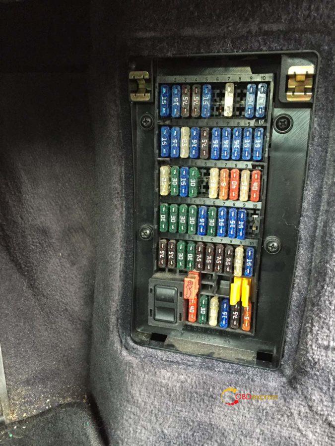
There are 4 clips on the side of the fuse box holding it in place, using your blunt knife press it into each clip to release it.
The fuse we need to connect to is B7. This is the second row from the top and the 4th fuse in from the right (as indicated by the number sequence).
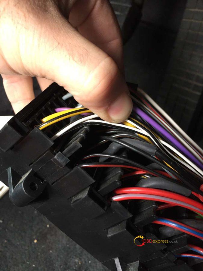
Run the cable along the bulk of cables to the fuse box so you know what length you need and trim the cable down.
Find the black wire and using a snap-lock connector, attach your cable.
My 1m wire was black as well and you can see that running off to the right of the picture.
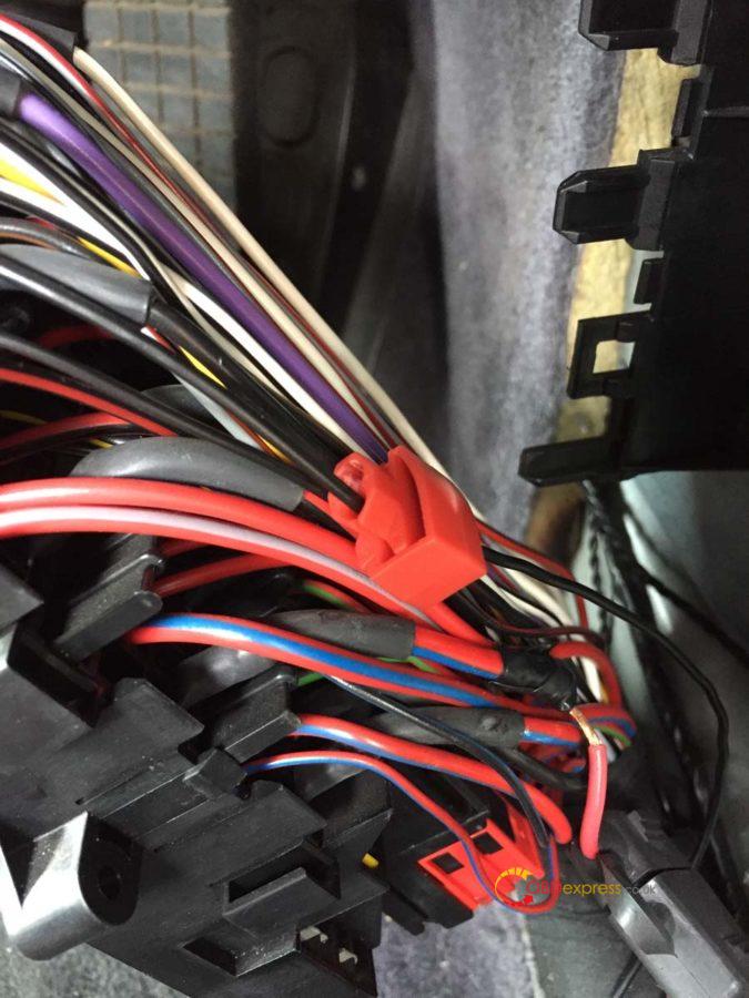
You can see the black cable just under the white and black one I’m holding. It crosses over a brown and black cable.
Tidy the cables up and push the fuse box back into its holder. Using some cable ties attach the new wire to the bulk of wires to keep it tidy. Put the carpet surround back and you’re done.
Now take a drive to your local OPC and get them to enable the cruise control coding in the DME (or anyone with a PST2 or PIWIS Tester in engineering Mode).
Project "Fix my broken indicators and retro-fit cruise controlâ€.…completed it mate!
Credits to @ Leon1davies.
Source of PIWIS Tester 3 with engineering Mode that can enable the cruise control coding.
http://www.obdexpress.co.uk/wholesale/piwis3-porsche-tester-diagnostic-tool.html
Source:http://blog.obdexpress.co.uk/2020/03/21/how-to-retrofit-cruise-control-of-porsche-996-2002-2005/
Posted by: OBDexpress.co.uk at
08:50 AM
| No Comments
| Add Comment
Post contains 2483 words, total size 33 kb.
March 17, 2020
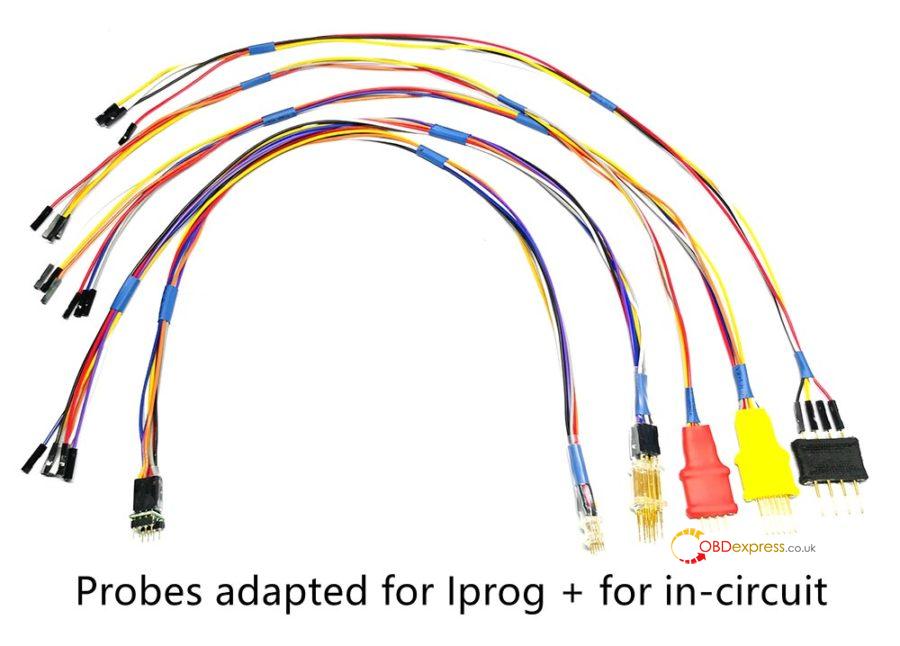
Look at the 5 probe adapters:
Testable ECU programmers:
iprog+ clone:yes
xprog:yes
More are testing.
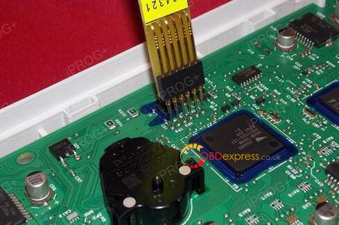
Purpose:
With the aboveprobe adapters, you can use iprog+ clone or xprog without welding the lines, for example, when you use Iprog to program the dashboard of 584321, just put the probes adapter at the contact points without welding, the job will be easier.

Price:
5 probe adapters price: 46EURO
http://www.obdexpress.co.uk/wholesale/probes-adapters-for-iprog-xprog-m.html
Iprog+ Iprog Pro With 7 Adapters Plus Probes Adapters:139EURO
http://www.obdexpress.co.uk/wholesale/iprog-pro-full-version-plus-probes-Adapters.html
xprog + 5 probe adapters price: 214EURO
http://www.obdexpress.co.uk/wholesale/xprog-v612-ecu-programmer-plus-probes-adaters.html
Enjoy!
Posted by: OBDexpress.co.uk at
03:30 AM
| No Comments
| Add Comment
Post contains 115 words, total size 3 kb.
March 12, 2020
Xentry Diagnosis Kit 3 user guide is available at:
Size: 113 pages
Thanks for @ Joseph~ sharing, I do not recommend anyone to buy this device cloned as MB can brick it anytime. latest Xentry has 3 timebombs that can take action anytime
stick with MB SD C4 DoIP, without batteries of course, to avoid getting bricked !
MB SD C4 DoIP user manual:
- How to setup MB SD Connect C4 Plus Wi Fi?
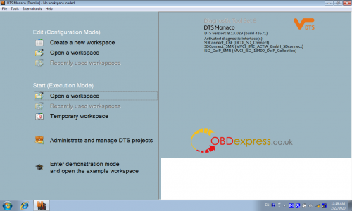
- How to Setup DTS Monaco software for MB SD C4 DoIP Plus?
- How to setup DOIP on MB SD Connect PLUS?
- MB SD Connect C4 DOIP XENRTY Test BENZ E213
DTS MONACO and Vediamo user guide:
Have the two Moe Diatronic training books.


C3 & C4 tech support:http://www.obdexpress.co.uk/wholesale/mb-star-series/
Source:http://blog.obdexpress.co.uk/2020/03/11/xentry-diagnosis-kit-3-user-guide-c4-user-guide/
Posted by: OBDexpress.co.uk at
07:16 AM
| No Comments
| Add Comment
Post contains 135 words, total size 19 kb.
March 11, 2020
Car model and ECU type:
BMW E60 530d
it's a dde 5 (m50d57a0) (bosch edc16c31) cas 2
It got water damage on the ecu and it fried it.
Purpose:
Got a new ecu with the same numbers but need a tool to read isn from cas, write to ecu and change vin on ecu.
E60 Bosch edc16c31 ECU programmer advice:
Possible solution 1:
You can do a BDM read with KTAG, that that will give You the option to read MPC/External Flash/EEPROM. You can do the full read and make a backup, so You will not be worried after something goes bad. For ISN change You need the EEPROM read. Than find on this forum BMW ISN tool, that will help You read and modify the ISN number in dumps.
It would be better if You had the original EDC unit, so You could just read and copy EEPROM, that would be way easier. But as You don't have it, than You will need to buy one more tool. Get R270+ or Xprog, because You will also need to read CAS EEPROM. As You can't read the original ISN of Your car with tools You have unfortunately. These tools aren't too expensive, and as You are a beginner I'd suggest R270+. The software includes a photo instructions on where to connect BDM cables in CAS unit, so it will be rather fast and easy job.
With R270 read only CAS EEPROM, You don't need Flash. Open BMW ISN editor, load the EDC dump, load CAS dump and in ISN editor You will find the option to copy ISN from EDC to CAS, click on that, then click on DDE<->CAS synchronization in ISN editor, save the new dumps and write them back to EDC and to CAS. That should give You the programmed and synchronized immobilizer.
After that, connect the ISTA-P to the car, click the option, that You changed the engine control unit and calculate the programming plan. ISTA will suggest You the correct software number to program, and You can do that with ISTA or load the soft with WINKFP, depending what software You prefer. It might seem complicated, but it's really easy job to do. And if You ever find Yourself in such situation again, do not throw the damaged ECU until You copied the memories. It really can help to make things easier and faster.
Possible solution 2:
There are tools which can help you but as you don't want to spend money on them so
You have this option....you have to buy DME and CAS with keys or with keys
1. If you bought DME, CAS and keys just install in the car and itwill start....reprogram the modules using Autel MS908 P or ISTA-P so it'll change VIN number to match your vehicle
2. If you bought DME, CAS only then you have to make key for it and reprogram the modules using Autel MS908P or ISTA-P
or you have to at least buy FVDI/SVCI to read ISN from DME and it'll give you the option to write that ISN in CAS2
ISN on this model is 4 digits so its easie.
(Although I use Original AVDI and it work great for this stuff but again too much expensive if you will not be doing in regular basis)
***However, someone don't agree and says:
You can't change VIN in CAS with ISTA or WINKFP, You still need programmer unfortunately. AVDI is rather expensive (but great tool, have the original and it's pretty handy). Also after fitting the used CAS there will be manipulation dot on instrument panel and the mileage between CAS and Instrument will be different. In some countries that's actually a big problem right now.
That's all.
Thanks!
No images attached, for the details of the ecu programmers mentioned above, please refer to www.obdexpress.co.uk
Source:http://blog.obdexpress.co.uk/2020/03/10/bmw-e60-530d-ecu-programming-tool-advice/
Posted by: OBDexpress.co.uk at
02:43 AM
| No Comments
| Add Comment
Post contains 651 words, total size 5 kb.
March 05, 2020
One user feedback his VCM2 IDS V86 need the activation code to active your license (shown as following image). One question, how to get the license?
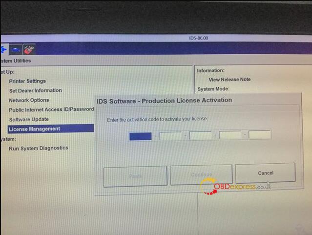
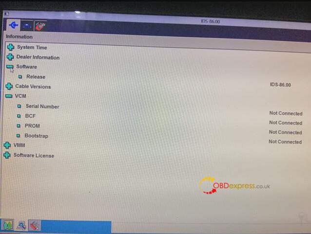
Obdexpress.co.uk engineer replied:
Because the patch is not installed, there is one patch in the CD.
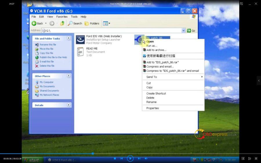
You can also watch the below youtube video:
Good luck!
Source:http://blog.obdexpress.co.uk/2020/03/05/vcm2-ids-v86-activation-code-how-to-get-it/
Posted by: OBDexpress.co.uk at
05:57 AM
| No Comments
| Add Comment
Post contains 62 words, total size 3 kb.
March 03, 2020
Tested version:
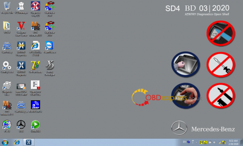
03.2020 XENTRY Openshell XDOS HDD
http://www.obdexpress.co.uk/wholesale/2020-03-mb-star-sd-c4-hdd.html
03.2020 XENTRY Openshell XDOS SSD (running faster & more stable)
http://www.obdexpress.co.uk/wholesale/202003-mb-sd-c4-software-ssd.html
Security:Safe, you can use it relief.
v03/2020 Xentry OpenShell XDOS is confirmed working perfectly with 12v/24v Mercedes Car, Bus, Truck, Sprint, Smart ,(from 1989 to the 2019 year)
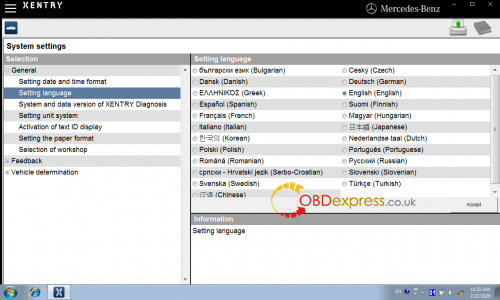
Support languages: English, Croatian, Czech, Danish, Dutch, Finish, French, German, Greek, Hungarian, Italian, Japanese, Korean, Polish, Portuguese, Romanian, Russian; Spanish, Swedish, Turkish, Chinese.
Software confirmed!
1.D-A-S / Xentry 2020.03……….Confirmed!
the automatically Diagnosis Assistance System, Concise interface and straightforward operation with IB M high-quality computer can realize the quick and accurate code reading and the whole car system testing
2.W-I-S net 2018.11……….Confirmed!
Workshop Information System Supply the whole view of the wiring diagram in a car,component location diagram and maintenance method. What you do is to enter the chassis number, and then you will get the manufacture data, engine configuration and the car model -all in detail.
3.EPC.net 2018.11……….Confirmed!
Electronic Parts Catalog
4.ST Finder ……….Confirmed!
Part Location Finder options: 2008 and 2016
- STARUTILITIES……….Confirmed!
the movement management system and self-test
- SDMEDIA 2014……….Confirmed!
- PL73 2019 ……….Confirmed!
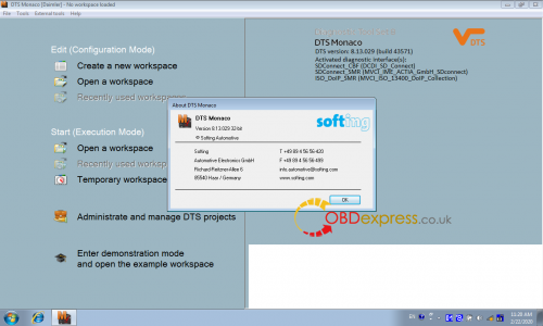
- DTS Monaco 8.13.029
- HHT-WIN
- Vediamo 5.01.01
- Vediamo Database 2019
Function confirmed!
Coding……….Confirmed!
Full Diagnostics……….Confirmed!
reading trouble code……….Confirmed!
erasing trouble code……….Confirmed!
reading live-data……….Confirmed!
adaptation……….Confirmed!
maintenance……….Confirmed!
component testing……….Confirmed!
information consultation……….Confirmed!
component location diagram……….Confirmed!
wiring diagram……….Confirmed!
flash code……….NOT worked!
(Notice: mb sd software will no support online coding after v2019.12, if you wantSCN Online Coding Function, pls buy v2019.09 sd c4 software:V09/2019 HDD,V09/2019 SSD)
Source:http://blog.obdexpress.co.uk/2020/03/02/03-2020-xentry-das-xdos-download/
Posted by: OBDexpress.co.uk at
02:27 AM
| No Comments
| Add Comment
Post contains 250 words, total size 6 kb.
February 28, 2020
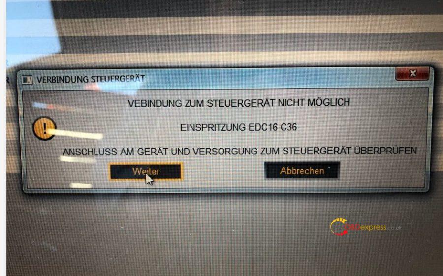
Renault can clip V193 problem: During normal operation, the CAN and USB LEDs flash. After a few minutes, the device started ticking, and then a "connection lost" message appeared. Then, the LED stays on.
Sometimes the device ticks again after a few seconds, I can continue, sometimes not. Then I had to plug it back in and start over.
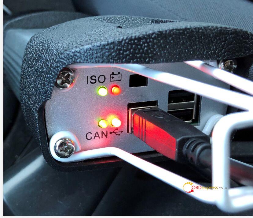
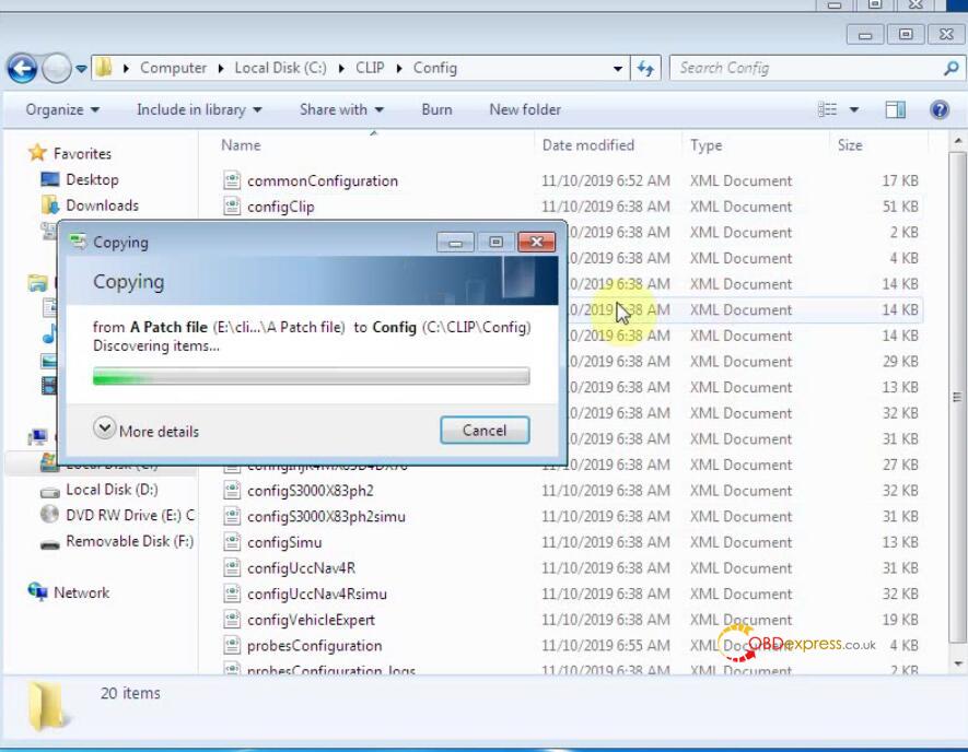
obdexpress.co.uk engineer working solution:
Please free download the following two files, then copy them to Computer -> Local Disk (C![]() ->Clip -> Config to replace the original ones. Then problem will be solved.
->Clip -> Config to replace the original ones. Then problem will be solved.
probesConfiguration_logs.xml
https://mega.nz/#!9V4ADQhb!Iv2O0iJ3eKTpoFqmmEf82gz_9MW5W5ioQ5NtPpRpBSQ
probesConfiguration.xml
https://mega.nz/#!MN5SWACb!ESkykTpTq2U9HvhZqQZj9hJQTA8sEdHpbRojbmuDxqs
Good luck!
Source:http://blog.obdexpress.co.uk/2020/02/28/solved-v193-can-clip-renault-connection-lost/
Posted by: OBDexpress.co.uk at
03:27 AM
| No Comments
| Add Comment
Post contains 108 words, total size 3 kb.
February 27, 2020
It's confirmed Ford Mondeo 1,6 SCTi 160 HK odometer adjustment can be done by Digimaster 3. Go on reading for the procedure.
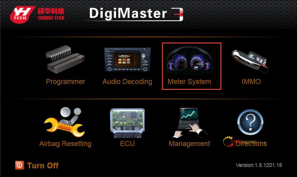
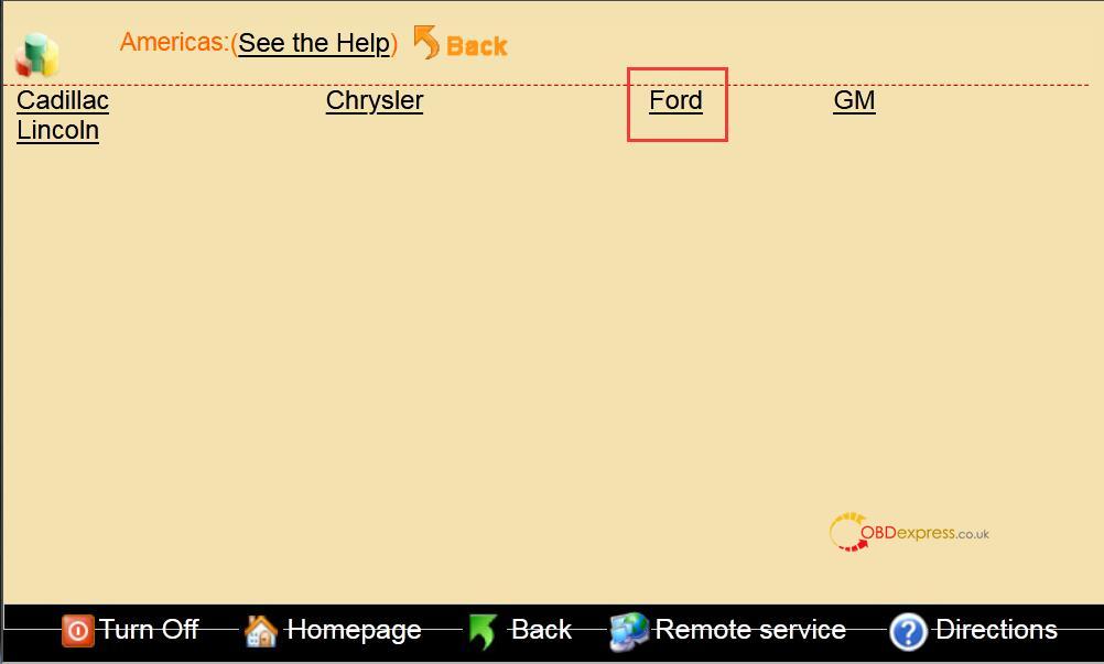
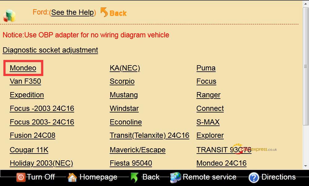
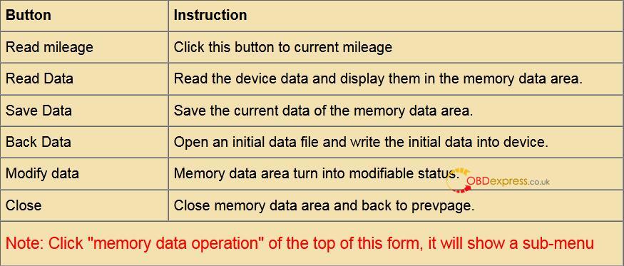
- Click on the "Meter system" button on the home page, then car series "Americas", then "Ford", then "Mondeo", then year.


- Remove chip or welding cable
It will shows the detail information after choose the corresponding model, as the chip model, power-map.
Based on the chip model and power-map (Because some odometer chip contains a multi-block, or there are other considerations) to find the chip on the odometer PCB, remember that direction then removed it, installed on universal adapter, If the original chips have been damaged or adjusted by the new chips please use the same model; This is the Split-free chip, Please connect the cable refer to the wiring diagram from software, and then plug the ICP to the 25 pin socket of the SET MASTER.
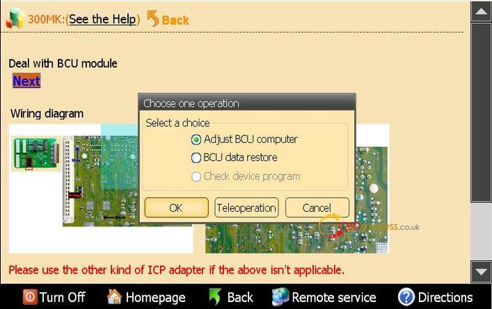
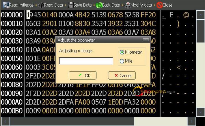
Click "OK" on the dialog box as the upper picture, the meter will read the device data immediately.
- Input mileage
1). Click "yes" the device will save the data of chip automatically,and will point its name and location.
2). The follow window means the original data of the chip have saved.
2.1). Input the mileage you want on the write box then click HOK".
2.2). For there are not only mileage data on the odometer chip, so please write the original data on the new chip before adjusting, then write the mileage.
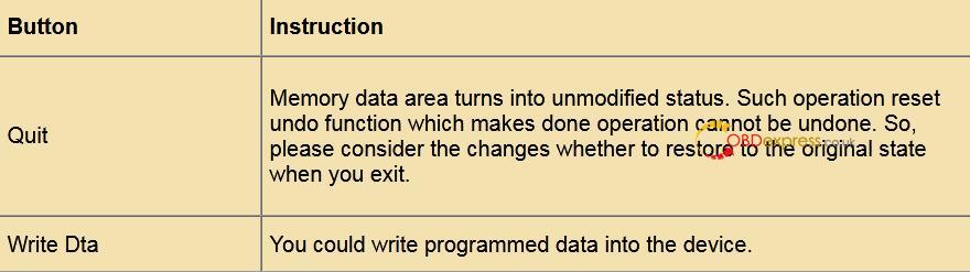
2.2.1) Click the "cancer* as the follow picture, then click "restore the original data", choose the original data to write the chip, the device supply the most of cars original data, if there is not, please collecting, take out the chip in the odometer, read the data then save it.
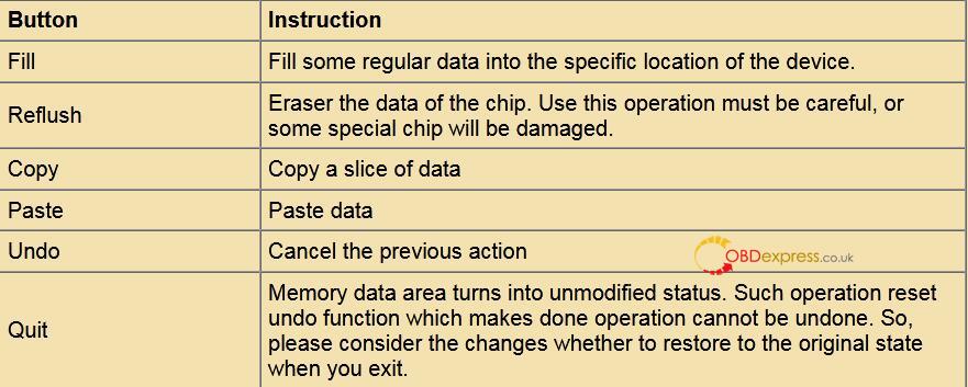
2.2.2). First close the memory data area after restoring data, then you can adjust mileage as above steps.
3). Quit after successful adjustment prompt, removed the welding line and then clean the circuit board.
- Modify data
If no need to modify the inner data of the chip after successful adjustment, please take the chip back odometer to finish the operation, or you can skip this step.
1). click "modify data", the data of memory data area will change into editable state, modify the data by cursor directly.
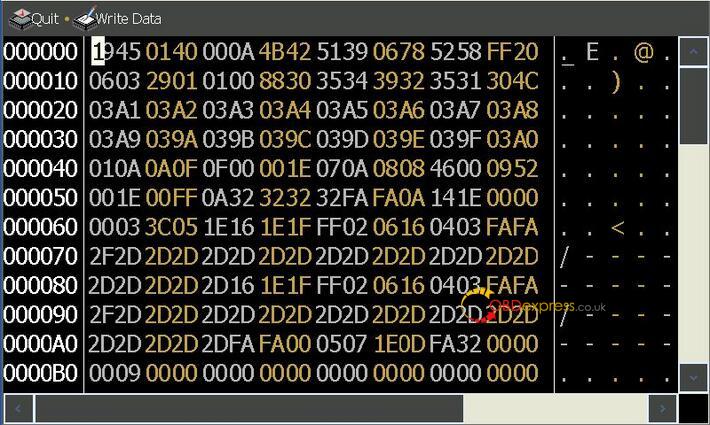
If the chip of the car model is IC type, then the interface is as follows when click "Modify data".
Enjoy!
Digimaster 3 tech support by www.obdexpress.co.uk
Source:http://www.mileageprogrammer.com/ford-mondeo-16-scti-160-hk-odometer-adjust-by-digimaster-3/
Posted by: OBDexpress.co.uk at
08:16 AM
| No Comments
| Add Comment
Post contains 416 words, total size 6 kb.
32 queries taking 0.1376 seconds, 149 records returned.
Powered by Minx 1.1.6c-pink.

